

Multiphase permanent magnet reluctance motor
A reluctance motor and permanent magnet technology, applied in electrical components, electromechanical devices, etc., can solve the problems of low torque density, large motor torque fluctuation, high vibration and noise of switched reluctance motors, and achieve reliability and safety High, high power density, the effect of reducing copper consumption
- Summary
- Abstract
- Description
- Claims
- Application Information
AI Technical Summary
Problems solved by technology
Method used
Image

Examples
specific Embodiment approach 1
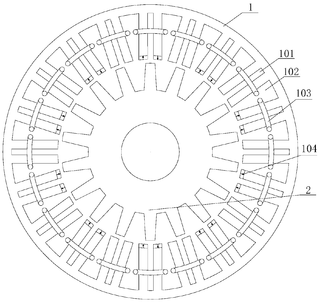
[0046] Specific implementation mode one: the following combination figure 1Describe this embodiment, the polyphase permanent magnet reluctance motor described in this embodiment includes a stator and a rotor, an air gap is formed between the stator and the rotor, the stator includes a stator core 1, a stator winding, and permanent magnets 104; the rotor includes a rotor Iron core 2; the rotor core 2 is cylindrical, and a plurality of rotor slots are equally spaced along the circumferential direction on the air-gap side surface of the rotor core 2; the plurality of rotor slots are formed on the air-gap side surface of the rotor core 2 Rotor teeth arranged at equal intervals;
[0047] The stator core 1 is cylindrical, and a plurality of stator slots 102 are equally spaced along the circumferential direction on the air gap side surface of the stator core 1, and a stator slot 2 101 is also opened between two adjacent stator slots 102, 20 stator teeth are formed, the number of ph...
specific Embodiment approach 2
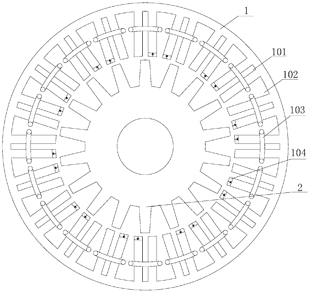
[0053] Specific implementation mode two: the following combination figure 2 Describe this embodiment, the polyphase permanent magnet reluctance motor described in this embodiment includes a stator and a rotor, an air gap is formed between the stator and the rotor, and the stator includes a stator core 1, a stator winding, and a permanent magnet 104;
[0054] The rotor includes a rotor core 2; the rotor core 2 is cylindrical, and a plurality of rotor slots are equally spaced along the circumferential direction on the air gap side surface of the rotor core 2; Rotor teeth arranged at equal intervals are formed on the side surface;
[0055] The stator core 1 is cylindrical, and a plurality of stator slots 102 are equally spaced along the circumferential direction on the air gap side surface of the stator core 1, and a stator slot 2 101 is also opened between two adjacent stator slots 102, 20 stator teeth are formed, the number of phases of the motor is 5 phases; the stator windi...
specific Embodiment approach 3
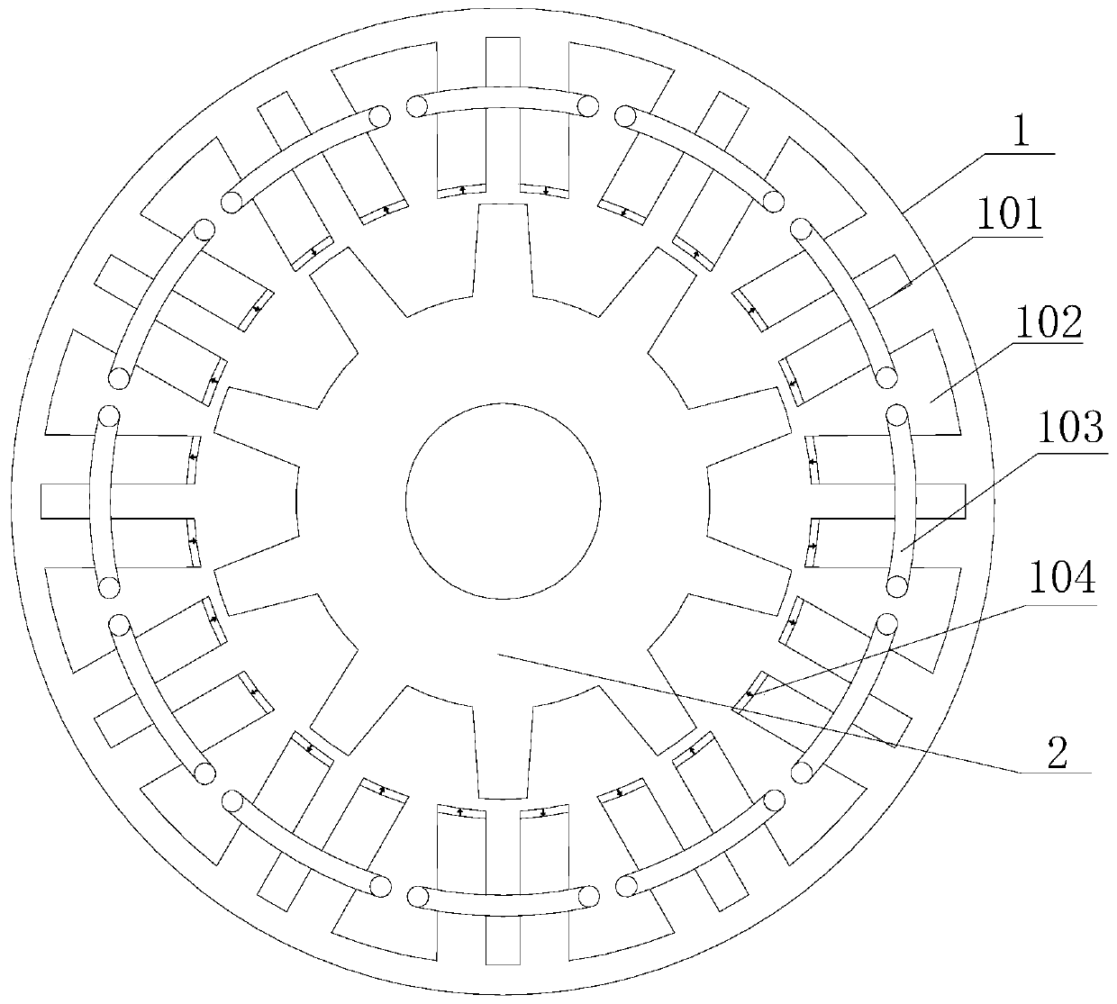
[0061] Specific implementation mode three: combination image 3 Describe this embodiment, the multiphase permanent magnet reluctance motor of this embodiment includes a stator and a rotor, an air gap is formed between the stator and the rotor, and the stator includes a stator core 1, a stator winding, and a permanent magnet 104;
[0062] The rotor includes a rotor core 2; the rotor core 2 is cylindrical, and a plurality of rotor slots are equally spaced along the circumferential direction on the air gap side surface of the rotor core 2; Rotor teeth arranged at equal intervals are formed on the side surface;
[0063] The stator core 1 is cylindrical, and a plurality of stator slots 102 are equally spaced along the circumferential direction on the air gap side surface of the stator core 1, and a stator slot 2 101 is also opened between two adjacent stator slots 102, 24 stator teeth are formed, the number of phases of the motor is 3 phases; the stator winding is a three-phase wi...
PUM
 Abstract
Description
Claims
Application Information