Eureka AIR delivers breakthrough ideas for toughest innovation challenges, trusted by R&D personnel around the world.

System for optical data interconnection

A technology for optical data and interconnection systems, applied in TV systems, transmission systems, and electromagnetic wave transmission systems adapted to optical transmission, and can solve problems such as high cost, large loss of pictures, large signals, and large size.

Active Publication Date: 2019-12-13
WINGCOMM CO LTD
View PDF14 Cites 3 Cited by
  • Summary
  • Abstract
  • Description
  • Claims
  • Application Information

AI Technical Summary

Problems solved by technology

Unfortunately, over long distances (e.g. 5 meters or more), the impedance of copper cables can cause large signal losses leading to artifacts (such as pixelation, optical flare or flicker) or even picture loss
These artifacts can be reduced by passive connection designs involving large or well-shaded copper cables, but this is expensive, bulky, and limits cable flexibility
Alternatively, active electronic modules such as signal boosters can be used to reduce signal loss, but these techniques are also expensive and can lead to the introduction of signal errors

Method used


Image

  • System for optical data interconnection
  • System for optical data interconnection
  • System for optical data interconnection

Examples


Embodiment Construction

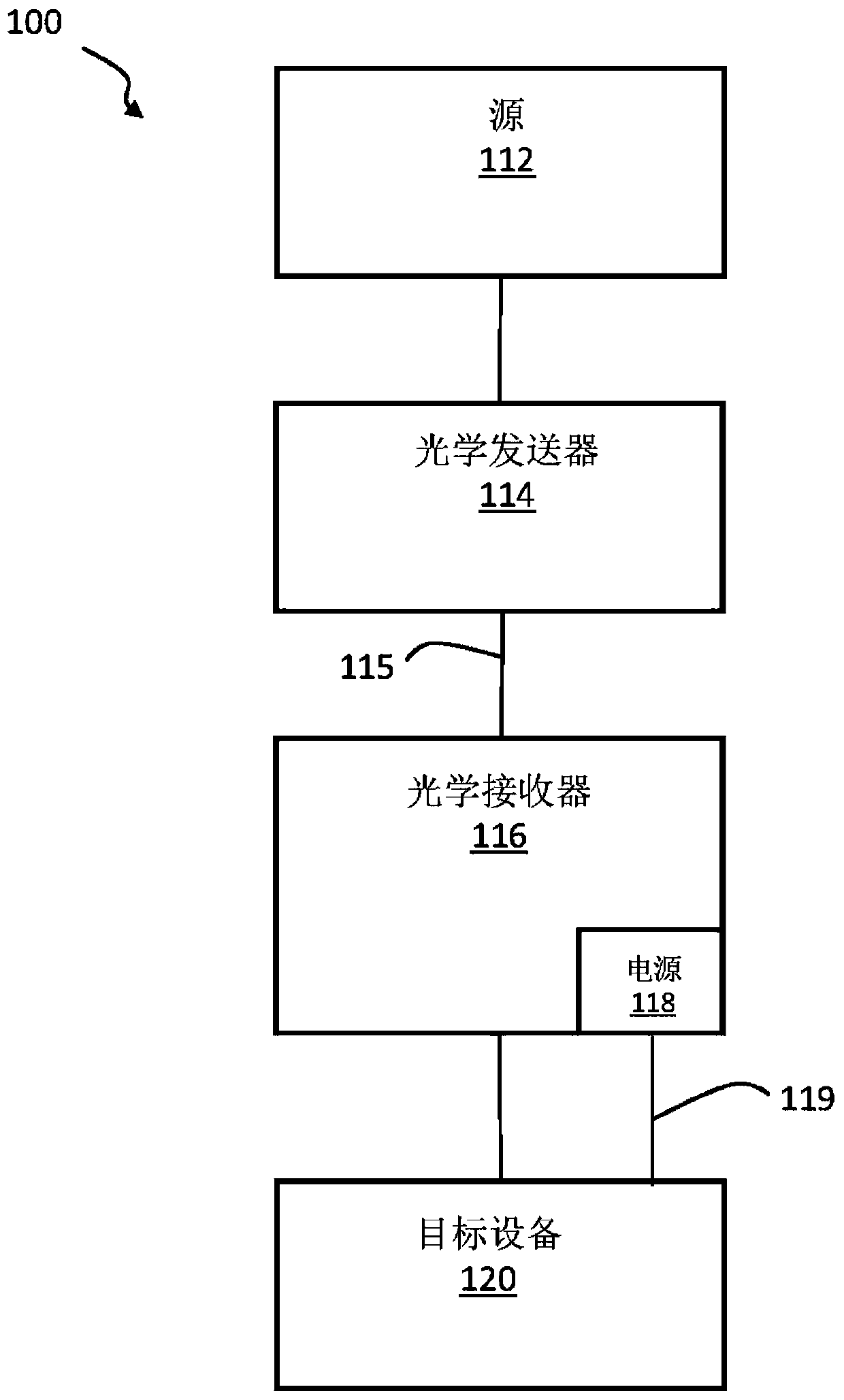
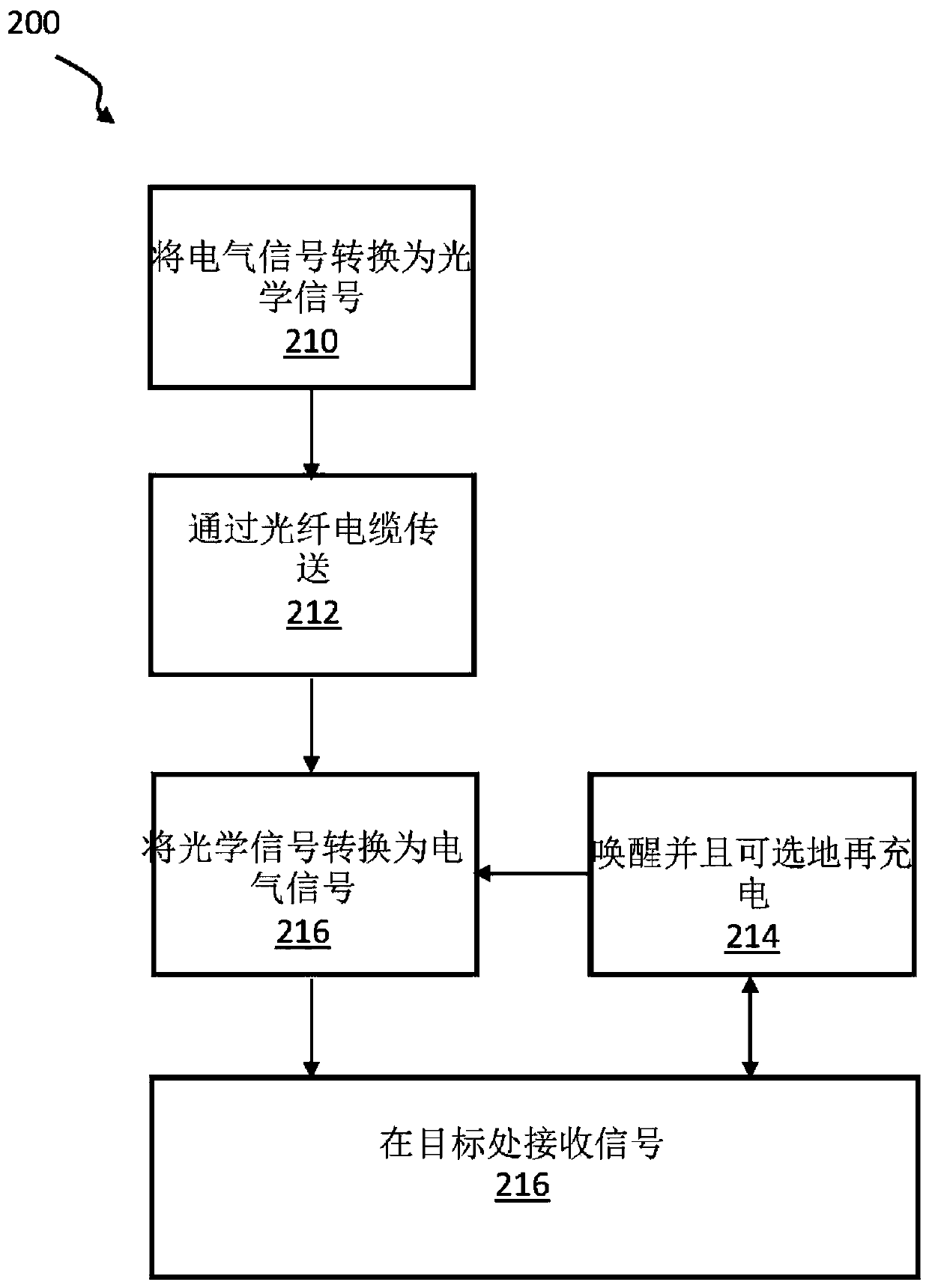
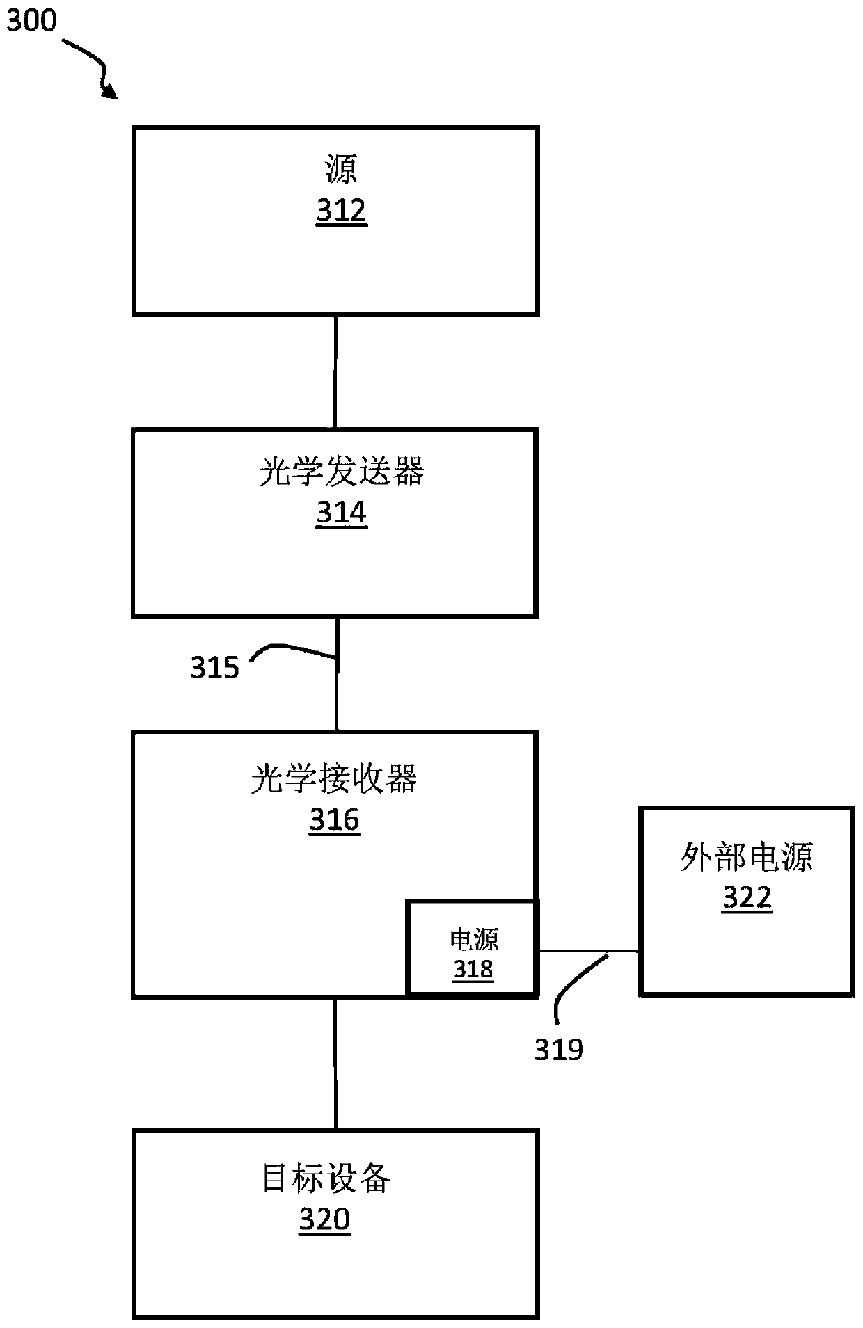
[0040] as in figure 1 As seen in , an optical interconnect system 100 capable of supporting conversion of electrical signals to optical signals and back to electrical signals is illustrated. The signal source 112 is connected to an optical transmitter 114, which acts as a first signal converter that converts the electrical signal received from the signal source 112 into an optical signal. One or more optical fibers 115 are used to transmit optically encoded data to an optical receiver 116 . The optical receiver decodes and acts as a second signal converter that converts the data into an electrical signal that is provided to the target device 120 . Optical receiver 116 may include a separate power supply module 118 which, in at least one embodiment, is connected to the target device via electrical power connection 119 .

[0041] Various signaling protocols are supported by the optical interconnect system. In some embodiments, the electrical signal may be provided by source 1...


PUM


Abstract

A system for optical data interconnection of a source and a target includes a first HDMI compatible electrical connector capable of receiving electrical signals from the source. A first signal converter is connected to the first HDMI compatible electrical connector and includes electronics for converting the TMDS electrical signal into an optical signal, and the electronics include an optical conversion device connectable to a source ground to reduce noise. At least one optical fiber is connected to the first signal converter. A second signal converter is connected to the at least one opticalfiber and includes electronics for converting the optical signal to a TMDS electrical signal. A power supply module for a second signal converter provides power to an electrical signal amplifier connectable to a target ground. A second HDMI compatible electrical connector is connected to the second signal converter and is capable of transmitting a signal to the target.

Description

[0001] Priority Application Information [0002] This application is based on U.S. Provisional Application No. 62 / 817,225 (“Optical Data Interconnect System”) filed March 12, 2019, the entire contents of which are incorporated herein by reference. technical field [0003] The present disclosure relates to systems for optical interconnects. In particular, a system and method for simulating an electrical HDMI interconnect to an optical system is described. Background technique [0004] High Definition (HD) signals are typically transmitted from one system to the other using cables carrying DVI (Digital Visual Interface) or HDMI (High Definition Multimedia Interface) signals. Conventionally, DVI / HDMI signals are conveyed over copper cables using Transition Minimized Differential Signaling (TMDS). In TMDS, video, audio and control data can be carried as 24-bit words on three TMDS data channels and a separate TMDS channel for clock information. It can also be carried on four T...

Claims


Application Information

Patent Timeline
IPC IPC(8): H04N7/22G02B6/42
CPCH04N7/22G02B6/42H04N21/615H04N21/43635H04B10/801H04B10/25751H04B10/25891H04B10/27H04B10/25H04B10/808H02J7/007
Inventor 白昀毛蔚王祚栋
Owner WINGCOMM CO LTD
Why Eureka
Eureka Blog
Learn More