
Vapour monitoring

A liquid target and particle technology, applied in electrical components, X-ray tube gas-filled materials, X-ray tube gas control, etc., can solve problems such as system performance degradation, window blurring, and lower cathode efficiency

Active Publication Date: 2019-12-13
EXCILLUM
View PDF6 Cites 0 Cited by
  • Summary
  • Abstract
  • Description
  • Claims
  • Application Information

AI Technical Summary

Problems solved by technology

This leads to gradual degradation of system performance as deposited debris can obscure the windows and reduce the efficiency of the cathode

Method used


Image

  • Vapour monitoring
  • Vapour monitoring
  • Vapour monitoring

Examples


Embodiment Construction

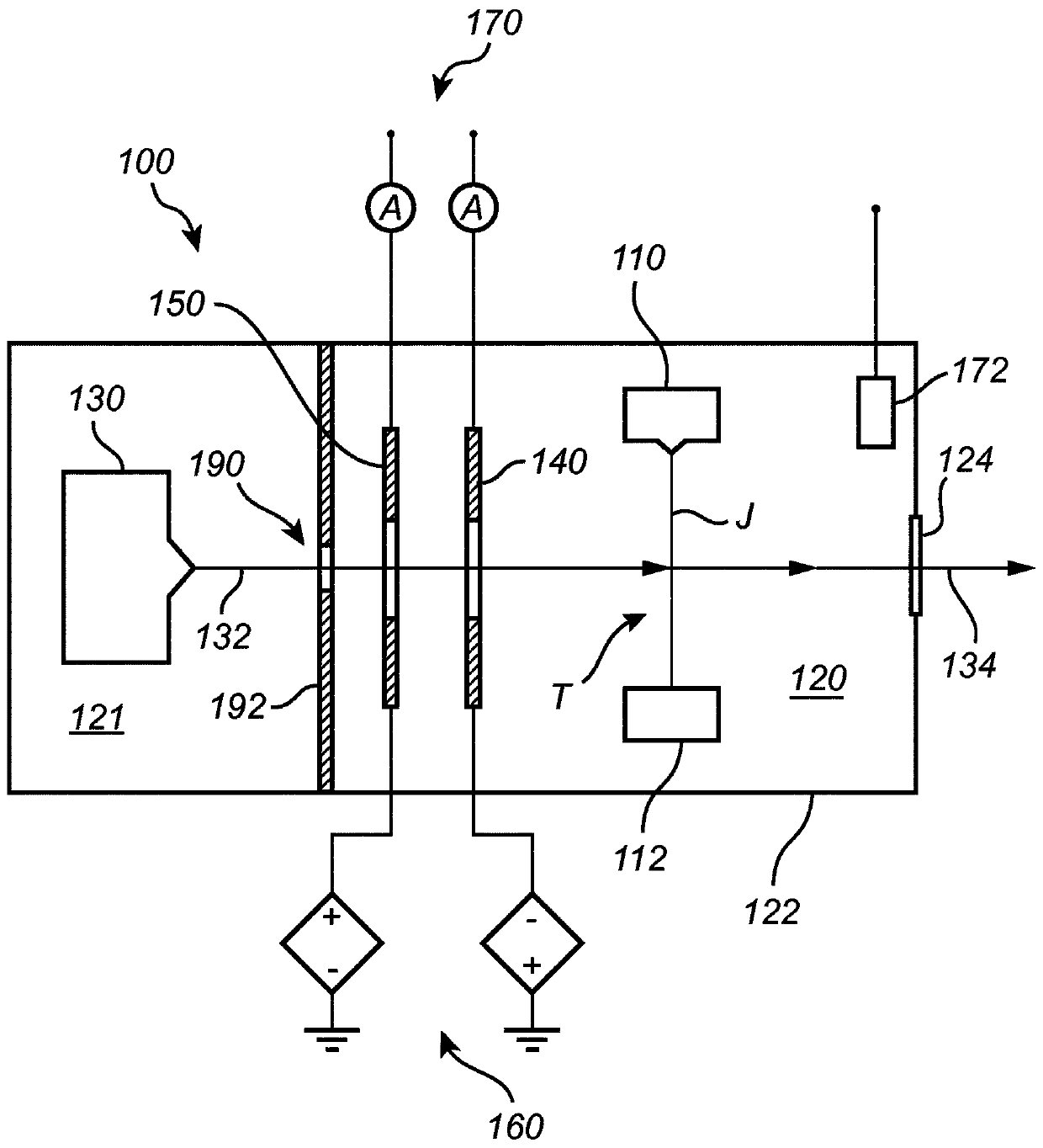
[0063] will now refer to figure 1 An X-ray source 100 according to an embodiment of the present invention is described. Such as figure 1 As indicated in , the vacuum chamber 120 may be defined by an enclosure 122 and an X-ray transparent window 124 that separates the vacuum chamber 120 from the surrounding atmosphere. X-rays 134 may be generated by an interaction region T in which electrons from electron beam 132 may interact with target J.

[0064] An electron beam 132 directed towards the interaction region T may be generated by an electron source 130, such as an electron gun 130 comprising a high voltage cathode. The electron beam 132 may follow a trajectory or path between the electron source 130 and the interaction region T, wherein the trajectory may be adjusted by the configuration of the electron optics and / or the electron source. The electron source may further be controllable to allow adjustment of parameters of the electron beam such as for example beam current, ...


PUM


Abstract

A method for generating X-ray radiation is disclosed. The method comprises providing (10) a liquid target (J) in a chamber (120), directing (20) an electron beam (132) towards the liquid target such that the electron beam interacts with the liquid target to generated X-ray radiation (134), estimating (30) a number of particles produced from the interaction between the electron beam and the liquidtarget by measuring a number of positively charged particles in the chamber and eliminating a contribution from scattered electrons to the estimated number of particles, and controlling (40) the electron beam, and / or a temperature in a region of the liquid target in which the electron beam interacts with the target, such that the estimated number of particles is below a predetermined limit. A corresponding X-ray source is also disclosed.

Description

technical field [0001] The invention disclosed herein relates generally to electron impact X-ray sources comprising a liquid anode. In particular, the invention relates to techniques for controlling an X-ray source based on the estimated number of particles produced by the interaction between an electron beam and a liquid target. Background technique [0002] A system for generating X-rays by irradiating a liquid target is described in the Applicant's International Application PCT / EP2009 / 000481. In these systems, an electron source comprising a high voltage cathode is utilized to generate a beam of electrons that impinges on a liquid target. The target is preferably formed by a jet of liquid metal disposed within the vacuum chamber. During operation, the location in space where a part of the liquid jet is struck by the electron beam is called the interaction region or point of interaction. X-ray radiation generated by the interaction between the electron beam and the liqu...

Claims


Application Information

Patent Timeline
IPC IPC(8): H01J35/20H01J35/30H01J35/04
CPCH01J35/20H01J35/30H05G1/30H01J2235/082H01J2235/1204H01J2235/1225H01J35/116H01J35/147H01J35/16H01J2235/20H05G1/265H05G1/36
Inventor 波尔·塔克曼汤米·图希玛
Owner EXCILLUM
Learn More