Laser stitch welding device and welding method thereof

A technology of laser welding and welding method, which is applied in the field of depth-adaptive laser stitch welding device, and can solve problems such as difficulty in controlling the penetration depth of laser stitch welding

Active Publication Date: 2019-12-17
CRRC QINGDAO SIFANG CO LTD
View PDF5 Cites 4 Cited by
  • Summary
  • Abstract
  • Description
  • Claims
  • Application Information

AI Technical Summary

Problems solved by technology

[0005] An object of the present invention is to provide a depth-adaptive laser stitch welding device, and also provide a welding method for the penetratio...

Method used


Image

  • Laser stitch welding device and welding method thereof
  • Laser stitch welding device and welding method thereof
  • Laser stitch welding device and welding method thereof

Examples


Embodiment 1

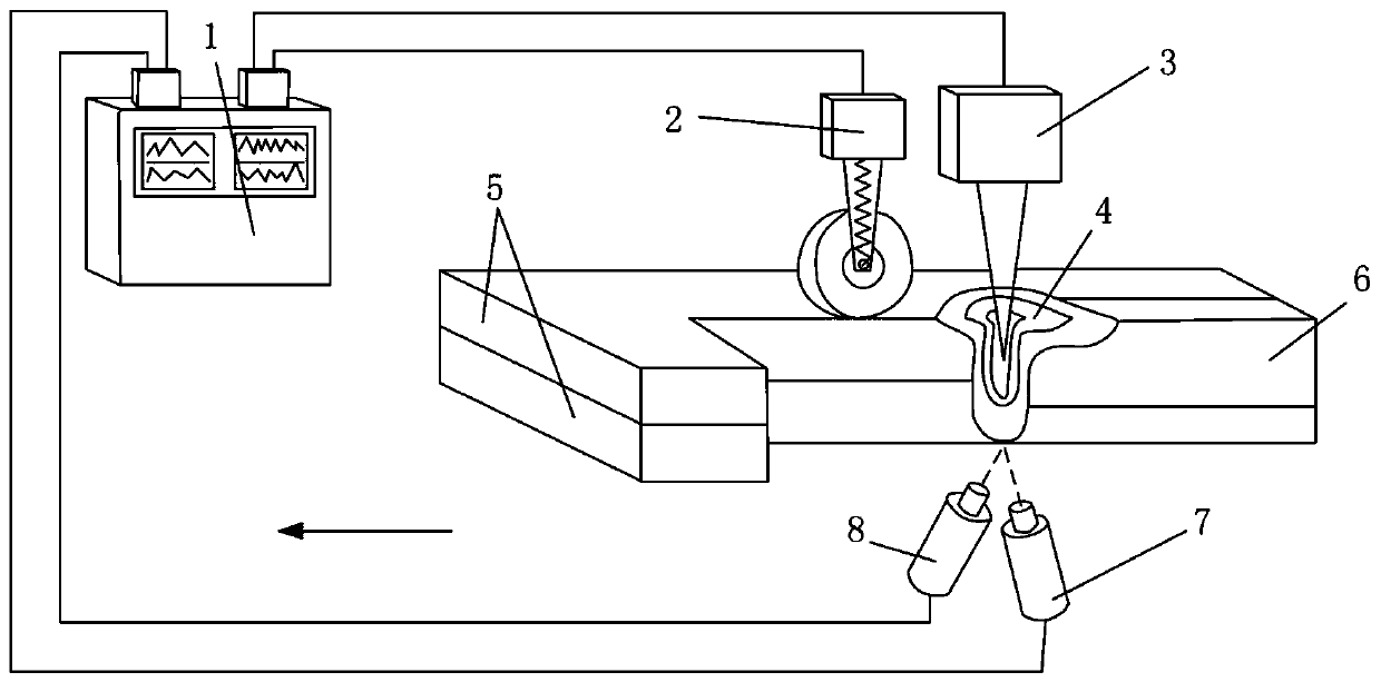
[0066] refer to figure 1 , stack the middle thin plate (i.e. the plate to be welded 5), the laser welding torch head (belonging to the laser welding assembly 3) is welded on the upper part of the middle thin plate, and a temperature (sensitive) sensor and a thermal image sensor 7 are arranged on the back of the middle thin plate relative to the bottom layer, The temperature (sensitive) sensor collects the backside temperature in real time, and the thermal image sensor 7 collects the red-hot image of the weld seam 6 in real time, and transmits the temperature value and the red-hot image of the weld seam 6 to the control system including the controller 1, and records the temperature in real time in the control system Curve and thermal image image, and compare with temperature standard line, thermal image diameter standard line.

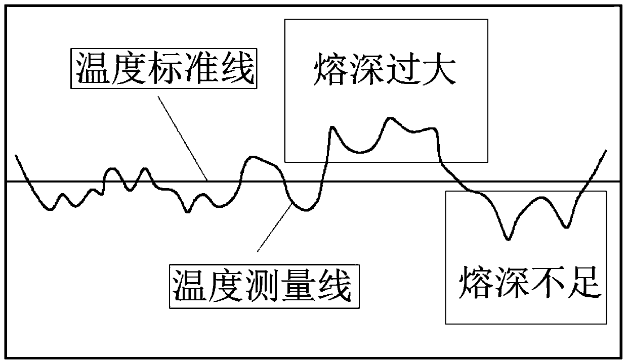
[0067] Such as figure 2 , 3 As shown, when the depth of penetration is insufficient, the heat transfer on the back of the bottom plate to be welded ...

Embodiment 2

[0071] This embodiment provides different control methods for different comparison results in embodiment 1.

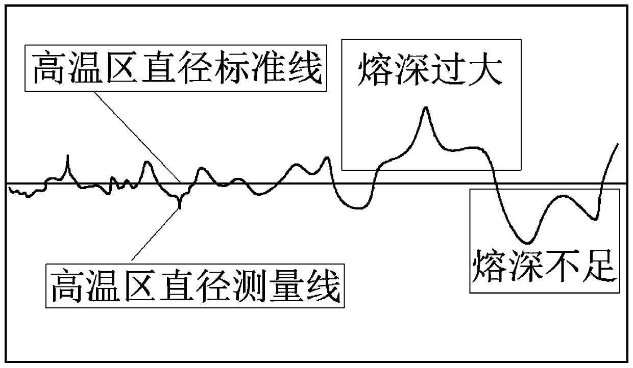
[0072] The temperature curve and thermal image images are recorded in real time in the control system, and compared with the temperature standard line and the thermal image diameter standard line.

[0073] Such as figure 2 , 3 As shown, if the depth of penetration is too large, the heat transfer on the back of the bottom plate to be welded 5 is large, the surface temperature is higher than the standard value, the high temperature area of ​​the thermal image increases, and the diameter is greater than the standard value on the diameter standard line. At this time, the laser energy is reduced. Increase the defocus of the laser spot, or use the pulsed laser output mode (the three can be adjusted at the same time, or one or two can be selected), so as to reduce the welding penetration. In addition, in some cases, the pressing force of the pressing roller can be appropri...


PUM


Abstract

The invention relates to the technical field of welding, in particular to a fusion depth self-adaption laser stitch welding device and a welding method thereof. The fusion depth self-adaption laser stitch welding device comprises a laser welding module for releasing laser beams to stacked plates to be welded from the front surface, a pressing piece for adjusting the distance between the stacked plates to be welded, a detecting module for detecting welding parameters of the stacked plates to be welded from the back surface, and a controller for adjusting the pressing degree of the pressing piece and/or operation parameters of the laser welding module in real time according to the welding parameters detected by the detecting module. Such welding parameters as the back surface temperature andred images of welding lines during welding of the plates to be welded are detected in real time; and a control system controls the pressing degree of the pressing piece or the operation parameters ofthe laser welding module according to the welding parameters to timely adjust the welding process to realize the fusion depth self-adaption stable control of the welding lines.

Description

technical field [0001] The invention relates to the field of welding technology, in particular to a depth-adaptive laser stitch welding device and a welding method thereof. Background technique [0002] Laser welding is widely used in various fields of industrial production due to its advantages such as high energy density, large weld depth-to-width ratio, small heat-affected zone, good welding quality, and easy automation. As an important material connection method, stitch welding is also widely used in actual production. [0003] The welding of double-layer plates of medium and thin plates is generally required to be welded on the surface of the upper plate when the two plates are stacked. The bottom plate has a certain depth of penetration but not penetration. More advanced welding methods generally use laser welding, but In the process, there is a problem that the welding penetration is difficult to control, or the bottom plate penetration is insufficient, or the penetr...

Claims


Application Information

Patent Timeline
IPC IPC(8): B23K26/24B23K26/70
CPCB23K26/24B23K26/702B23K26/034B23K26/244B23K26/037B23K37/0408
Inventor 韩晓辉马国龙张志毅毛镇东
Owner CRRC QINGDAO SIFANG CO LTD
Why Eureka
Try Eureka