Solar unmanned aerial vehicle wing structure

A solar unmanned aerial vehicle and wing structure technology, which is applied in the direction of wings, wing shapes, unmanned aircraft, etc., can solve the problem that solar cell array planes are difficult to fit and install, the operation process is complicated, and the production is complicated, etc. solve the problem, and achieve the effect of low structural area density of the whole machine, light wing structure and meeting the design requirements

Active Publication Date: 2019-12-17
NORTHWESTERN POLYTECHNICAL UNIV
View PDF11 Cites 2 Cited by
  • Summary
  • Abstract
  • Description
  • Claims
  • Application Information

AI Technical Summary

Problems solved by technology

[0003]Solar UAV requires ultra-light structure design, that is, it is required to meet the strength and rigidity requirements of the structure within a given weight range; in addition, solar UAV uses Solar radiation, it uses photocells to convert solar energy into electrical energy, and drives the propeller to rotate through the motor to generate flight power. In order to improve the laying rate of solar panels, the surface of the wing is generally covered with solar panels. Due to the limitation of radian and installation structure, the rigid and fragile solar cell array plane is difficult to adapt to the fitting and installation of large curvature changes on the wing; the third aspect is that solar aircraft often increase the size of the wing panels. area, wing-body fusion is often performed, and the fuselage is small or designed without a fuselage. Therefore, in order to reduce the loading pressure of the fuselage, a large amount of space inside the wing is used, and the drone can be aerodynamically unloaded, and the battery is loaded in the wing is a good problem-solving strategy
[0004] At present, in the disclosed solar drone wing preparation technology, there is no disclosure of the solar drone wing fabrication method, and the wing fabrication is often It cannot meet the requirements of the design, and its shape depends entirely on the manual skill level of the operator, resulting in asymmetrical aerodynamic shape, etc., which ultimately leads to a decline in the design level
Regarding the installation of solar panels, the patent CN 106379516 B introduces the technology from encapsulation to installation of flexible solar panels. The operation process is relatively complicated, and rapid production and installation cannot be realized.
In addition, for the battery in the wing, the patent CN 106240798 B introduces a technical solution for loading the battery on the wing spar. The battery is stored inside the wing spar, which requires the assistance of a cooling device, which is complicated to manufacture, and cannot be quickly installed and replaced.

Method used


Image

  • Solar unmanned aerial vehicle wing structure
  • Solar unmanned aerial vehicle wing structure
  • Solar unmanned aerial vehicle wing structure

Examples


Embodiment Construction

[0030] This embodiment is a solar unmanned aerial vehicle wing structure.

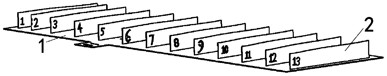
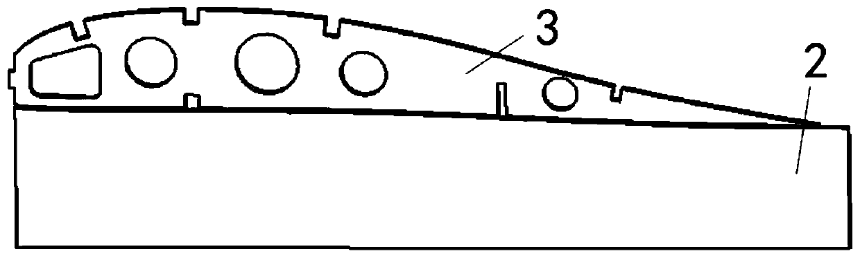
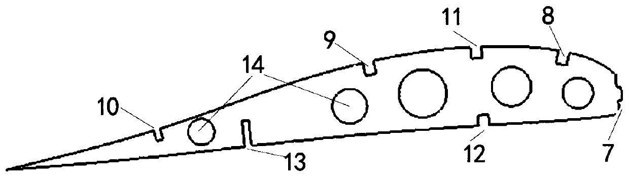
[0031] refer to Figure 1 to Figure 8 , the wing structure of the solar unmanned aerial vehicle in this embodiment is composed of a frame bottom plate 1, a frame clamp 2, a wing rib 3, a battery 4, a solar panel 5 and an upper pressure frame 6, wherein the frame clamp 2 are arranged in sequence on the frame bottom plate 1, and the frame clamping plates 2 are multiple pieces, and the upper part of each frame clamping plate 2 has a wing rib 3 for cooperating installation. The upper surface of the wing rib 3 is provided with the first slot 8 of the rib stringer, the second slot 9 of the stringer, and the third slot 10 of the stringer, and the slot 11 of the upper beam of the wing rib is located in the first slot of the rib stringer 8 and the second slot 9 of the stringer, and the rib upper beam slot 11 and the rib lower beam slot 12 are slotted symmetrically and have the same shape, the rib rear wall soc...


PUM


Abstract

The invention discloses a solar unmanned aerial vehicle wing structure. The solar unmanned aerial vehicle wing structure is composed of a frame base plate, frame clamping plates, wing ribs, storage batteries, a solar cell panel and upper pressing frames, wherein the frame clamping plates are sequentially arranged on the frame base plate, the wing ribs are arranged at the upper parts of the frame clamping plates in a matched mode, stringer slots, upper beam slots and lower beam slots are formed in the upper surfaces of the wing ribs, rear wall sockets are located at the bottoms of the wing ribs, wing leading edge supporting bosses are arranged at leading edges of the wing ribs, and the multiple wing ribs, wing rib upper beams, wing rib lower beams, stringers and rear walls form a wing skeleton. According to the solar unmanned aerial vehicle wing structure, when the skeleton is manufactured, after the contour of a wing is restrained by adopting a frame and the upper pressing frames, thesolar cell panel is glued, the storage batteries are loaded in the wing, and other devices are supplemented in the reserved positions after gluing and fixing. The wing structure is light, the upper pressing frames are used to ensure that the solar cell panel is firmly bonded, the curvature of the contour of the wing is met, so that the solar cell panel can be kept under a good light condition in aflight state, and the energy acquisition rate is increased.

Description

technical field [0001] The invention relates to an unmanned aerial vehicle wing structure, in particular to a solar unmanned aerial vehicle wing structure, which belongs to the technical field of solar unmanned aerial vehicles. Background technique [0002] A solar-powered drone is an unmanned aerial vehicle powered by solar radiation. It uses photovoltaic cells to convert solar energy into electrical energy, and drives the propeller to rotate through a motor to generate flight power. With its unique advantages of long battery life, no pollution, and large-scale monitoring, solar-powered drones can realize the friendly construction of ecological civilization in the true sense. [0003] Solar-powered drones require ultra-light structure design, that is, within a given weight range, to meet the strength and stiffness requirements of the structure; in addition, solar-powered drones use solar radiation, which uses photocells to convert solar energy into electrical energy, which ...

Claims


Application Information

Patent Timeline
Patent Type & Authority Applications(China)
IPC IPC(8): B64C3/10B64C3/18B64D27/24
CPCB64C3/10B64C3/187B64D27/24B64U50/19Y02T50/50
Inventor 周洲白帆王正平赵忻左阅闻
Owner NORTHWESTERN POLYTECHNICAL UNIV
Why Eureka
Try Eureka