Three-phase separator system used in gas well liquid discharging process and using method

A three-phase separator and process technology, which is applied in earthwork drilling, wellbore/well components, valve operation/release devices, etc., can solve the problems of poor separation quality and difficult gas-liquid separation, and achieve good separation quality Effect

Pending Publication Date: 2019-12-17
BC P INC CHINA NAT PETROLEUM CORP +1
View PDF15 Cites 8 Cited by
  • Summary
  • Abstract
  • Description
  • Claims
  • Application Information

AI Technical Summary

Problems solved by technology

[0012] The present invention overcomes the deficiencies of the prior art and provides a three-phase separator system and usage method used in the gas well drainage process, especially solving the problems of difficult gas-liquid separation and poor separation quality in the oil and gas industry. At the same time, it also solves the problem of recovery of natural gas and fracturing fluid in the drainage fluid after gas well pressure

Method used


Image

  • Three-phase separator system used in gas well liquid discharging process and using method
  • Three-phase separator system used in gas well liquid discharging process and using method
  • Three-phase separator system used in gas well liquid discharging process and using method

Examples


Embodiment 1

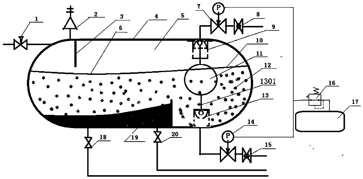
[0047] Reference figure 1 , Is a schematic structural diagram of embodiment 1 of the present invention, a three-phase separator system used in gas well drainage process, including

[0048] The three-phase separator housing 4 is provided with a separated sediment area and a separated liquid area at the bottom of the three-phase separator housing 4, and the top of the three-phase separator housing 4 is a separated gas area. A sewage outlet is provided, a liquid outlet is provided in the liquid area, and an exhaust outlet is provided in the gas area;

[0049] The gas-liquid inlet pipeline is connected to the three-phase separator housing 4, and the gas-liquid inlet pipeline is also connected with a gas-liquid inlet control valve 1;

[0050] The sewage pipe is connected with the sewage outlet of the separated sediment area in the three-phase separator shell 4;

[0051] A drain line, which is in communication with the drain port of the separated liquid zone in the three-phase separator hou...

Embodiment 2

[0057] Reference figure 1 , figure 2 with image 3 Compared with Embodiment 1, the difference of this embodiment is that the exhaust port is provided with an exhaust valve 9, the drain port is provided with a drain valve 13, and one end of the float valve 11 is connected to the exhaust valve. 9 is connected, and the other end of the float valve is connected with the drain valve 13. The two valves of the first pneumatic regulating valve 7 and the second pneumatic regulating valve 14 adopt pneumatic regulating valves of the same model, structure and working mode.

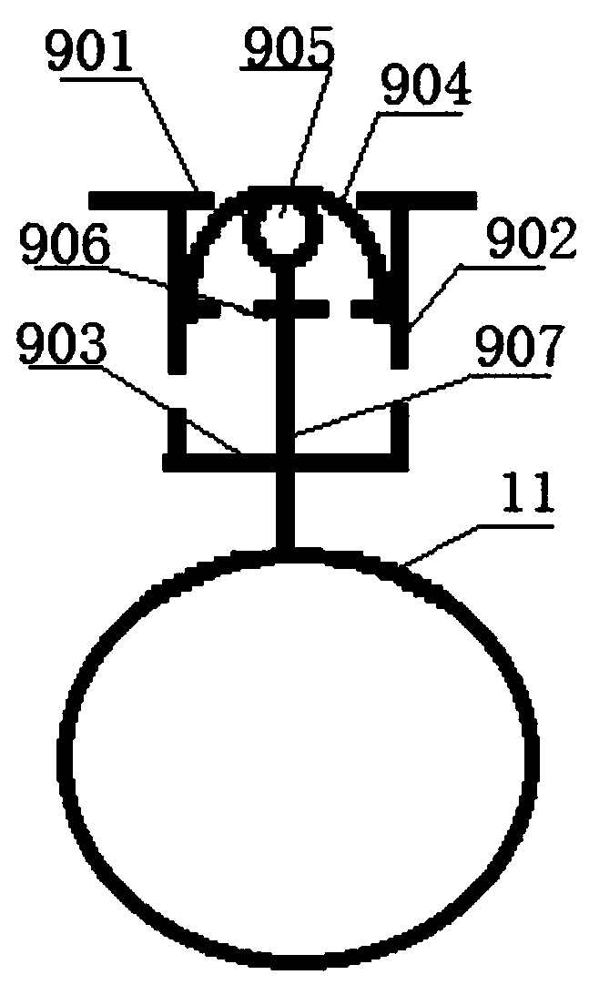
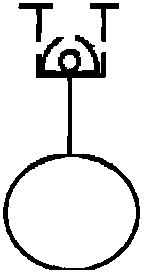
[0058] Preferably, the float valve includes a spherical float 11, an upper float connecting rod 907, a lower float connecting rod 1301, and a balance valve 905. One end of the spherical float 11 is connected to the exhaust valve 9 through the upper float connecting rod 907, and the spherical float 11 The other end is connected to the drain valve 13 through the lower float connecting rod 1301, and the ends of the upper f...

Embodiment 3

[0061] Compared with embodiment 2, the difference of this embodiment is: the exhaust valve 9 and the discharge valve 13 both include a valve seat 901, a valve housing 902, a valve displacement baffle 903, a valve head 904 and a balance Valve displacement baffle 906, valve seat 901 is connected to the inner wall of three-phase separator housing 4 around the exhaust port, one end of valve housing 902 is connected to valve seat 901, and the other end of valve housing 902 is connected to valve displacement baffle 903. The head 904 is located in the valve housing 902 and can move up and down. The valve head 904 has a semi-spherical structure. The valve head 904 of the semi-spherical structure has a hollow structure. The bottom is connected with a balance valve displacement baffle 906. The balance valve 905 floats upward. The sub-link 907 penetrates the balance valve displacement baffle 906 and is located in the valve head 904. The balance valve 905 and the connected upper float link ...


PUM


Abstract

The invention relates to the technical field of gas and liquid separation, in particular to a three-phase separator system used in a gas well liquid discharging process and a using method. Different from an existing control method, 1, a liquid level is not controlled to run at a certain height in a separator, but the liquid level is controlled to run between a liquid outlet and a gas outlet; 2, the two gas and liquid outlets adopt pneumatic pressure adjusting valves of the same model and the same parameter for control, so that the two outlets are equal in adjusting pressure, and it is guaranteed that the separator is steady in work pressure; 3, the gas pressure adjusting values of the two gas and liquid outlets are controlled through one pressure adjusting valve, so that the two pneumaticadjusting valves are equal in control gas pressure, and therefore the pressure is equal, that is, the pressure in a separator tank is smooth and steady, and good separating is guaranteed; and 4, whenthe gas outlet contains liquid drops, it is only needed to adjust the control gas pressure of the pressure adjusting valve high, and then gas and liquid separating can be achieved; and if the liquid outflow and gas outflow amounts are both very small, the control gas pressure of the pressure adjusting valve is adjusted small to lower return pressure on a well opening, and then normal liquid discharging of a gas well can be achieved.

Description

[0001] Technical field [0002] The invention relates to the technical field of gas-liquid separation, in particular to a three-phase separator system used in a gas well drainage process and a method of use. Background technique [0003] The three-phase horizontal separator uses the principle of gravity separation to separate the three phases of oil, gas and water. The upper part of the inner cavity of the separator is an air chamber, and the gas outlet is at the upper part; the weir plate divides the lower part of the container into an oil chamber and a water chamber. The fluid entering the separator first reaches the upper part of the water chamber. The lower part is water, the upper part is oil, and the space above the oil is natural gas. The height of the weir plate is set at 1 / 2 of the height of the container when it leaves the factory, so we must ensure that the water level is lower than the height of the weir plate during the work, and the oil level is up to 3 / 4 of the leve...

Claims


Application Information

Patent Timeline
Patent Type & Authority Applications(China)
IPC IPC(8): E21B43/34F16K31/18F16K17/20
CPCE21B43/34F16K31/18F16K17/20
Inventor 邓继学孙虎王祖文张冕白明伟景志明曹欣欧阳伟平韩静静付中新
Owner BC P INC CHINA NAT PETROLEUM CORP
Why Eureka
Try Eureka