
Novel 10kV grounding device

A grounding device, a new type of technology, applied in the direction of the bendable lead wire device, connecting contact materials, etc., can solve the problems of violating the safety regulations of electric power work, artificial winding of the grounding wire, easy slipping of the grounding rod, etc., to avoid wire damage, high altitude Work safety and the effect of avoiding direct contact

Pending Publication Date: 2019-12-17
STATE GRID SHANDONG ELECTRIC POWER CO QIHE POWER SUPPLY CO
View PDF0 Cites 1 Cited by
  • Summary
  • Abstract
  • Description
  • Claims
  • Application Information

AI Technical Summary

Problems solved by technology

[0005] 1) The electrical safety work regulations stipulate that when installing and removing the grounding wire, the human body must not touch the grounding wire or the ungrounded wire. It is possible to touch the grounding wire inadvertently, thereby violating the safety regulations of electrical work and posing potential danger;
[0006] 2) If there are live lines adjacent to or crossing over in the work site, the grounding wire may generate an induced current, which may cause electric shock and injury;
[0007] 3) The grounding rods are placed horizontally on the safety belt worn by the pedaling operator. When one of the grounding rods is held for hanging operation, the other two grounding rods are easy to slip off;
[0008] 4) The retraction and release of the grounding wire requires manual winding, and wire winding often occurs during the operation, which is easy to damage the grounding wire
[0009] At present, in the prior art, there is no safe and reliable related device for auxiliary ground connection

Method used


Image

  • Novel 10kV grounding device
  • Novel 10kV grounding device
  • Novel 10kV grounding device

Examples


Embodiment

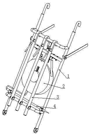
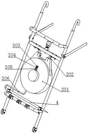
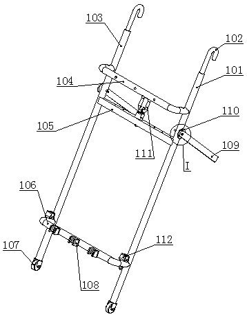
[0039] Such as Figure 1-Figure 6 As shown, a new type of 10kV grounding device includes a pylon 1, a ground wire, a ground pin 4, and three hook-type ground rods 3. The pylon 1 includes a first vertical rod 101, a second vertical rod 103, and an upper horizontal rod. 104 and the lower cross bar 106 are welded to form an H-shaped frame. The first vertical bar 101, the second vertical bar 103, the upper cross bar 104 and the lower cross bar 106 are made of insulating materials. The top of the vertical rod 103 is fixed with a hook 102. The hook 102 is welded to the top of the first vertical rod 101 and the second vertical rod 103. The two hooks 102 are connected in the same direction. Three buckles 108 are fixed; the upper cross bar 104 is used to receive the hooks of the three grounding rods 3, and the three buckles 108 are respectively used to clamp the insulating rods of the three grounding rods 3; the grounding wire includes the first branch Line 203, second branch line 204,...


PUM


Abstract

The invention relates to a novel 10kV grounding device, which comprises a hanging rack, a grounding wire, a grounding pin and three hook type grounding rods, wherein the hanging rack comprises a vertical ladder frame formed by welding a first vertical rod, a second vertical rod, an upper cross rod and a lower cross rod, lifting hooks are fixedly arranged at the tops of the first vertical rod and the second vertical rod, and three buckles are fixedly arranged on the lower cross rod; the upper cross rod is used for bearing hooks of the three grounding rods; the three buckles are respectively used for clamping insulating rods of the three grounding rods; a first branch line, a second branch line and a third branch line of the grounding wire are fixedly connected with the wiring terminals on the three grounding rods respectively, and a tail line of the grounding wire is fixedly connected with the wiring terminal on the grounding pin. By adopting the technical scheme, the high-altitude operation of hanging the grounding wire can be safer.

Description

Technical field [0001] The present invention relates to the field of power auxiliary tools, in particular to a new type of 10kV grounding device. Background technique [0002] The grounding wire is a wire directly connected to the earth, also known as a safety loop wire. In order to protect the personal safety of workers during power repairs and other operations, the grounding wire must be hung. [0003] At present, the conventional operation of hanging the grounding wire on the pole is: two people cooperate, one person works on the pole, and one person works on the ground. When the ground rod is hung, first, the operator of the pole step on the pole head, and hoist the three ground rods through the rope Put the three grounding rods horizontally on the safety belt worn by the pedaling staff. After the electric test is completed, take them one by one, and hang the grounding rods from low to high according to the height of the three wires in the sky. On the corresponding grounding r...

Claims


Application Information

Patent Timeline
IPC IPC(8): H01R4/64H01R4/66H01R13/72
CPCH01R4/66H01R4/64H01R13/72
Inventor 李振李贵民张志宏沈强李正昊
Owner STATE GRID SHANDONG ELECTRIC POWER CO QIHE POWER SUPPLY CO
Learn More