Dimmable LED drive circuit and control method

A technology of LED drive and LED circuit, applied in the direction of light source, electric light source, electrical components, etc., can solve the problems of increasing system loss, flickering light, unable to improve system application power, etc., to improve efficiency and stability, and improve small-angle flickering Effect

Pending Publication Date: 2019-12-17
MAXIC TECHNOLOGY CORPORATION
View PDF0 Cites 4 Cited by
  • Summary
  • Abstract
  • Description
  • Claims
  • Application Information

AI Technical Summary

Problems solved by technology

However, when the linear LED driver is used with the thyristor dimmer, in order to maintain the conduction of the thyristor, there must be a bleeder current, such as figure 1 As shown in the circuit, this will undoubtedly increase the loss of the system, reduce the efficiency of the system, and cannot increase the application power of the system
[0003] In addition, when the SCR conduction angle is small, there will be a flashing problem. This is because when the input peak voltage is close to the output LED lamp voltage after the SCR wave is cut, the SCR dimmer will have a serious asymmetry in the wave cutting. , so that the peak voltage of the thyristor after wave cutting is aperiodically greater than or less than the output LED voltage (such as figure 2 , Vin_pk1>VLED>Vin_pk2), resulting in drastic changes in the current of the LED lamp, and the frequency of the current change is less than the recognition frequency of the human eye, resulting in the phenomenon of flicker visible to the human eye

Method used


Image

  • Dimmable LED drive circuit and control method
  • Dimmable LED drive circuit and control method
  • Dimmable LED drive circuit and control method

Examples


Embodiment Construction

[0044] In order to express the technical solutions and advantages of the embodiments of the present invention more clearly, the technical solutions of the present invention will be further described in detail below with reference to the drawings and embodiments.

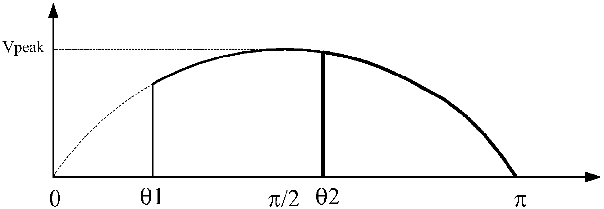
[0045] In the following embodiments of the present invention, the description of the conduction cutting angle of the thyristor dimmer 10 is uniformly used as an angle. image 3 A cycle of the rectified input voltage Vin is shown, where θ1 is the minimum initial conduction cutting wave angle, and the conduction cutting wave may occur at any angle between θ1-π. θ2 is one possible example of the initial turn-on chopping angle of a TRIAC dimmer, and θ1<θ2. π-θ1 and π-θ2 are conduction widths of the thyristor dimmer under angles of θ1 and θ2 respectively. The maximum value Vpeak of the input voltage Vin appears at an angle of π / 2.

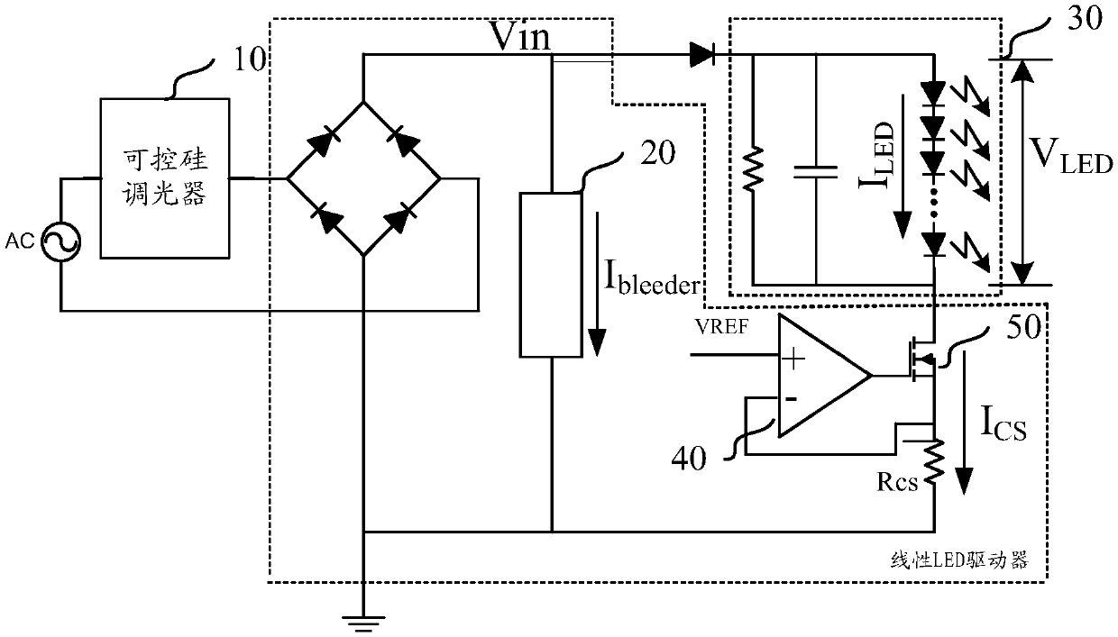
[0046] figure 1 It is a dimmable LED drive circuit in the prior art, which includes: AC...


PUM


Abstract

The invention provides a dimmable LED drive circuit and a control method. The dimmable LED drive circuit comprises a silicon controlled rectifier dimmer, a bleeder current circuit and an LED circuit.The bleeder current circuit provides a current required by the silicon controlled rectifier dimmer when an input voltage does not reach a conduction voltage of the LED circuit. The dimmable LED drivecircuit is characterized in that the dimmable LED drive circuit also comprises a silicon controlled rectifier shear wave angle detection circuit and a bleeder current control circuit. After the silicon controlled rectifier dimmer is conducted, the silicon controlled rectifier shear wave angle detection circuit acquires a first electrical parameter signal representing a silicon controlled rectifiershear wave angle; and the bleeder current control circuit compares the first electrical parameter signal with a first threshold to control the bleeder current circuit. Besides, an output current compensation circuit is further added and used for comparing the electrical parameter signal with a second threshold value to control the current of the LED circuit.

Description

technical field [0001] The invention relates to the field of LED drive circuits, in particular to a dimmable LED drive circuit and a control method. Background technique [0002] The LED drive usually adopts a linear drive mode, which has the advantages of simple structure, low EMI (Electro-Magnetic Interference, electromagnetic interference), and compatibility with most thyristor dimmers to achieve dimming. However, when the linear LED driver is used with the thyristor dimmer, in order to maintain the conduction of the thyristor, there must be a bleeder current, such as figure 1 As shown in the circuit, this will undoubtedly increase the loss of the system, reduce the efficiency of the system, and cannot increase the application power of the system. [0003] In addition, when the SCR conduction angle is small, there will be a flashing problem. This is because when the input peak voltage is close to the output LED lamp voltage after the SCR wave is cut, the SCR dimmer will ...

Claims


Application Information

Patent Timeline
Patent Type & Authority Applications(China)
IPC IPC(8): H05B33/08H05B44/00
CPCH05B45/31H05B45/3575H05B45/395H05B45/14H05B45/40H05B45/37H05B45/345
Inventor 牟在鑫张攀
Owner MAXIC TECHNOLOGY CORPORATION
Why Eureka
Try Eureka