
Puncturing and radio frequency melting device

A radiofrequency ablation and puncture needle technology, applied in the field of medical devices, can solve the problems of difficult rotation, tissue damage, and artifact in patients with metal implants, so as to reduce the risk of contamination, reduce injuries, and avoid secondary needle insertion. Effect

Inactive Publication Date: 2019-12-20
LISHUI CENT HOSPITAL
View PDF5 Cites 3 Cited by
  • Summary
  • Abstract
  • Description
  • Claims
  • Application Information

AI Technical Summary

Problems solved by technology

At present, CT-guided percutaneous biopsy is the most common and widely used biopsy puncture, but due to the ionizing radiation of CT, the resolution of soft tissue images is not high, and some patients with metal implants have artifacts, making CT Guidance has certain limitations in judging tumor boundaries and positioning
In addition, if the ablation needle needs to be rotated during the ablation operation, since the part where the ablation needle inserts into the tissue is directly covered by the tissue, not only is it difficult to rotate, but it will also cause damage to the tissue

Method used


Image

  • Puncturing and radio frequency melting device
  • Puncturing and radio frequency melting device
  • Puncturing and radio frequency melting device

Examples


Embodiment 1

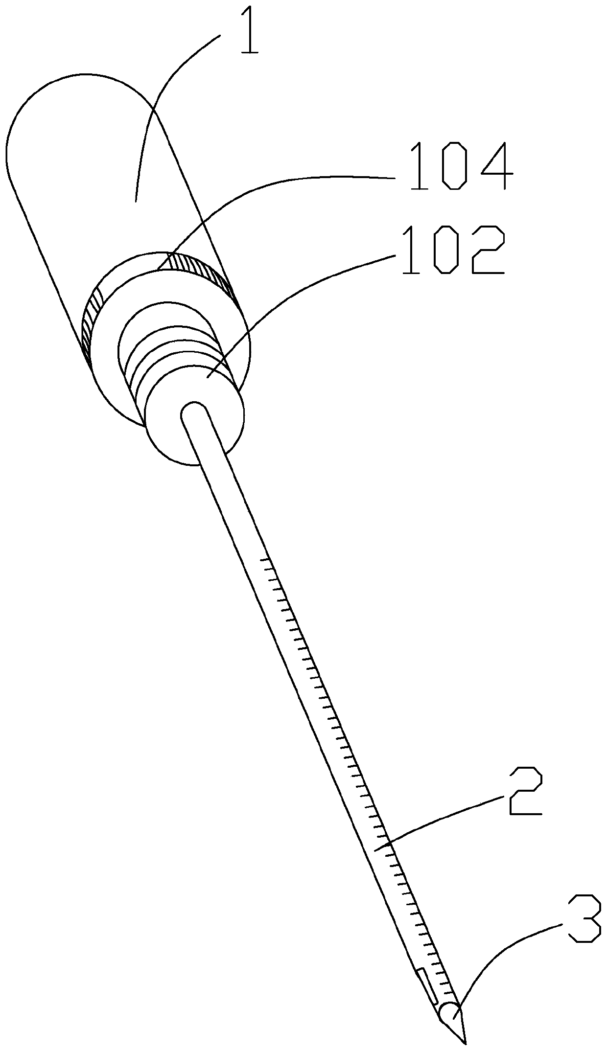
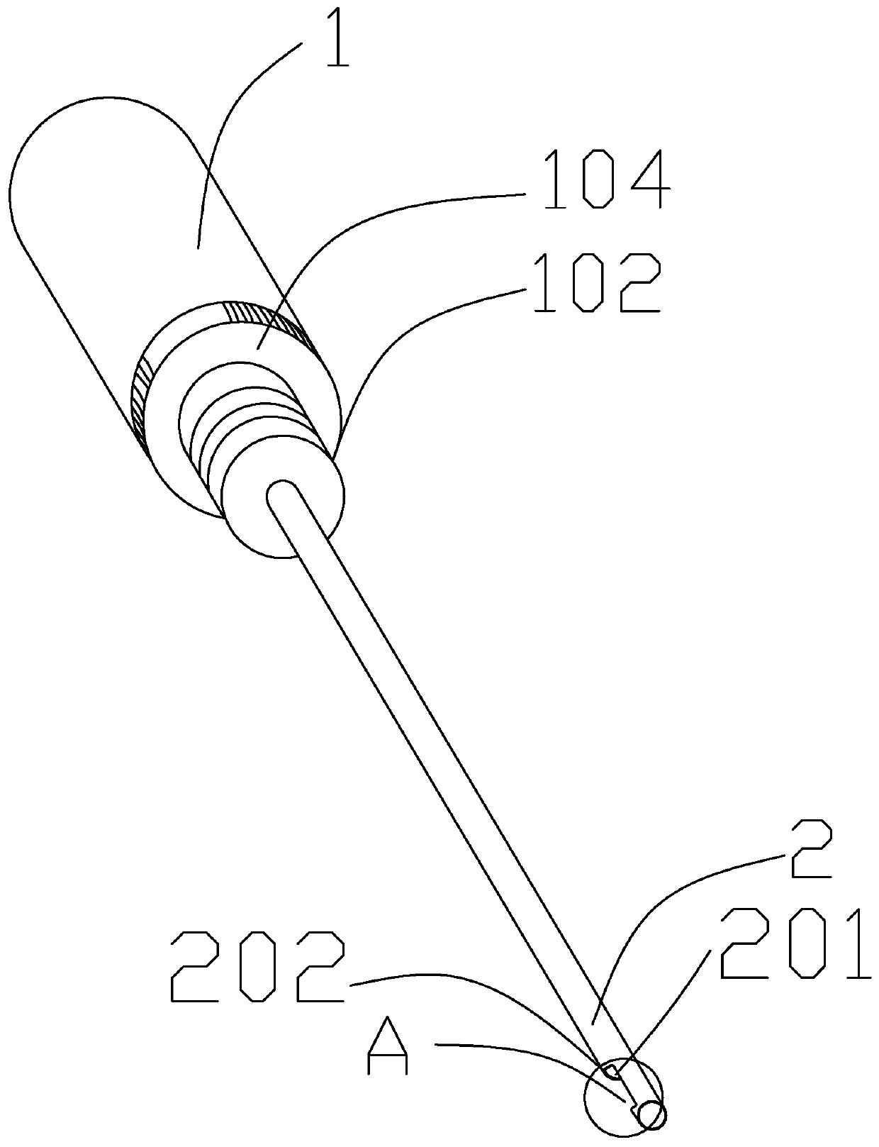
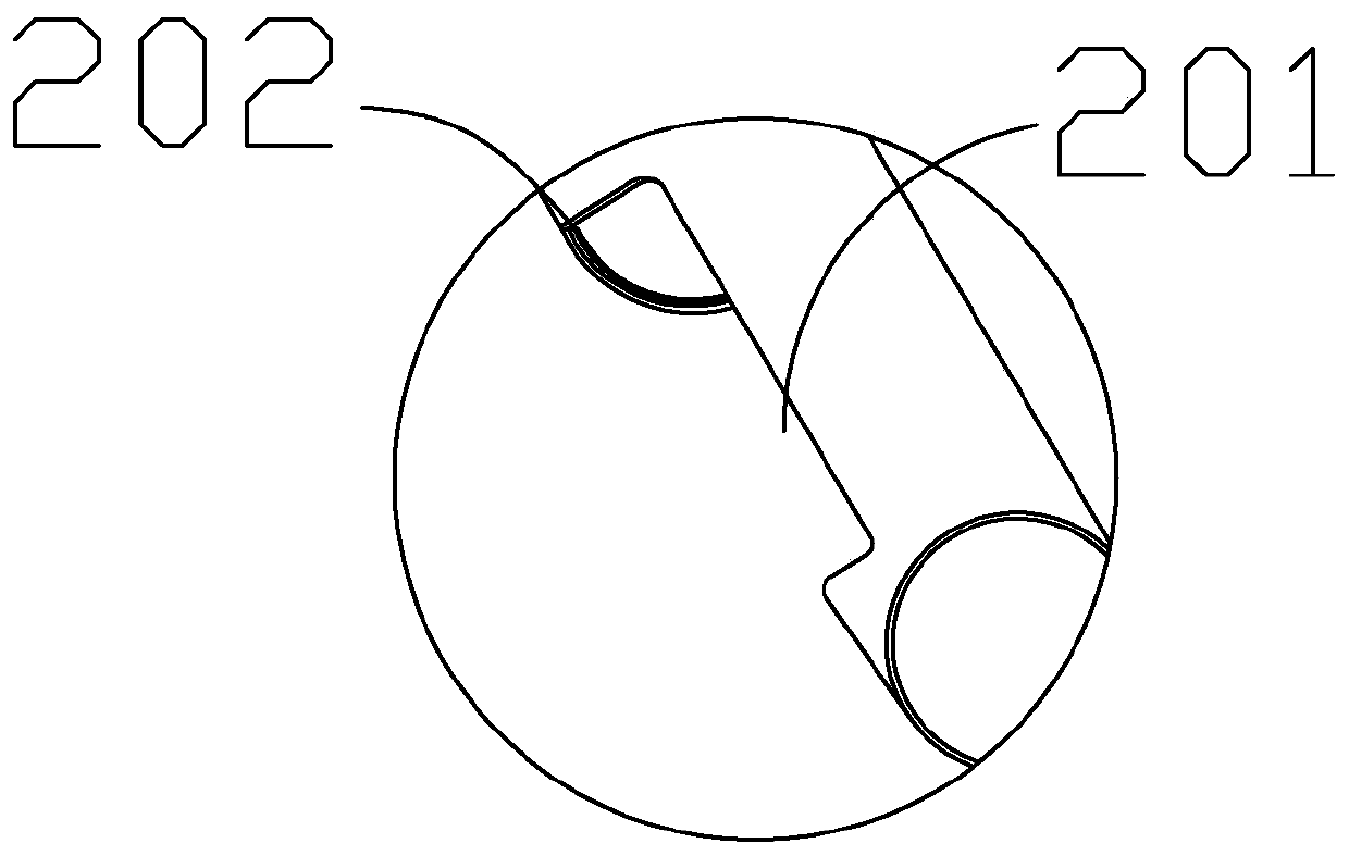
[0029] A puncture and radiofrequency ablation device, comprising an operating device 1, a hollow outer sleeve 2 and a puncture needle 3, the hollow outer sleeve 2 is mounted on the operating device 1, and the puncture needle 3 is inserted from the operating device 1 into the hollow and fixed on the operating device 1, the front end of the puncture needle 3 is provided with a point 301, the surface of the puncture needle 3 on the rear side of the point 301 is provided with a puncture opening 302, the puncture needle 3 Also be provided with a section of cavity 303 that links to each other with puncture opening 302 inside, also be provided with sampling opening 201 on the surface of outer casing 2, described puncture opening 302 is equal to described sampling opening 201, described puncture needle 3 and described overcoat The tubes 2 are matched with each other, the puncture needle 3 is inserted into the outer sleeve 2, the outer side wall of the puncture needle 3 and the inner si...

Embodiment 2

[0040] The difference from Embodiment 1 is that the piercing opening 302 is smaller than the sampling opening 201 . It must be that the front side of the puncture opening 302 is flush with the front side of the sampling opening 201 like this,

[0041] The puncture opening 302 is smaller than the sampling opening 201, and the puncture needle 3 just flattens the slice 202 that does not correspond to the flush side, forming a form in which one side is flattened and the other side bulges inward, and the tumor mass can also be cut well.


PUM


Abstract

The invention relates to the technical field of medical apparatus, in particular to a puncturing and radio frequency melting device. The puncturing and radio frequency melting device comprises an operating device, a hollow outer sleeve pipe and a puncture needle, wherein the hollow outer sleeve pipe is mounted on the operating device; the puncture needle is inserted in the hollow outer sleeve pipefrom the operating device, and is fixed on the operating device; a pointed head part is arranged at the front end of the puncture needle; a puncture opening is formed in the surface of the puncture needle on the rear side of the pointed head part; a section of cavity, which is connected with the puncture opening, is also formed in the puncture needle; and a sampling opening is also formed in thesurface of the outer sleeve pipe. According to the puncturing and radio frequency melting device disclosed by the invention, after puncture biopsy is completed under the guide of an outer sleeve pipe,a melting needle for a radio frequency melting operation is directly replaced, so that secondary needling can be effectively avoided, damages to a patient is reduced, and the risk of pollution is reduced.

Description

technical field [0001] The invention relates to the technical field of medical devices, in particular to a puncture and radiofrequency ablation device. Background technique [0002] For malignant tumors, whether there are mutations in the pathological classification, typing, or even genetic testing is the primary issue in the process of disease diagnosis and treatment, and the testing results directly determine the corresponding treatment plan. At present, CT-guided percutaneous biopsy is the most common and widely used biopsy puncture, but due to the ionizing radiation of CT, the resolution of soft tissue images is not high, and some patients with metal implants have artifacts, making CT Guidance has certain limitations in judging tumor boundaries and positioning. In addition, if the ablation needle needs to be rotated during the ablation operation, since the part where the ablation needle inserts into the tissue is directly covered by the tissue, not only is it difficult ...

Claims


Application Information

Patent Timeline
Patent Type & Authority Applications(China)
IPC IPC(8): A61B10/02A61B17/34A61B18/12
CPCA61B10/0266A61B17/3403A61B17/3421A61B17/3476A61B18/12A61B2017/3449
Inventor 纪建松陈敏江涂建飞赵中伟范晓希王海林叶亚妮
Owner LISHUI CENT HOSPITAL
Learn More