Automobile part ultrasonic washing machine

An auto parts and ultrasonic technology, applied in the field of parts cleaning, can solve the problems of complex installation and disassembly steps, single function, low utilization rate of cleaning solvents, etc., and achieve the effect of rapid storage and easy reuse.

Active Publication Date: 2019-12-20
爱阔特(上海)清洗设备制造有限公司
View PDF6 Cites 4 Cited by
  • Summary
  • Abstract
  • Description
  • Claims
  • Application Information

AI Technical Summary

Problems solved by technology

The currently used ultrasonic cleaning machine has a single function, and the steps of installing and disassembling parts are complicated, thereby reducing the cleaning efficiency, and the utilization rate of the cleaning solvent is low. Generally, it is drained after one cleaning, resulting in a lot of waste. In addition, when taking materials in the middle It is necessary for personnel to manually extend into the cleaning solvent, which is likely to cause a greater safety hazard to the health of the operator

Method used


Image

  • Automobile part ultrasonic washing machine
  • Automobile part ultrasonic washing machine
  • Automobile part ultrasonic washing machine

Examples


Embodiment 1

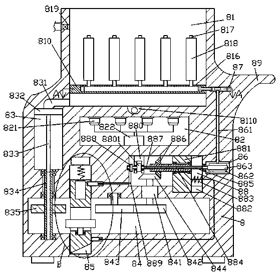
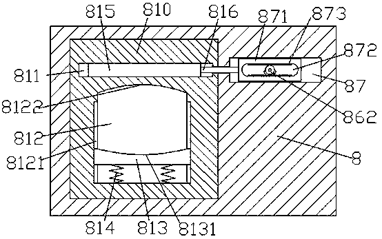
[0027] When cleaning is required, the parts to be cleaned are first installed in the clamping groove 812, so that the parts and the cleaning brush 818 are in contact with each other, and then the cleaning agent liquid supply valve 819 is opened to allow the cleaning liquid to enter the cleaning tank 81 Then, the ultrasonic transducer 821 is controlled by the ultrasonic generator 822 to generate ultrasonic waves. At the same time, the driving motor 841 drives the first bevel gear 844 to rotate, and then the first bevel gear 844 drives the second bevel gear 886 and the inner key rotary sleeve 884 Rotate, at this time, the second key shaft 887 and the first key shaft 885 are driven by the inner key rotating sleeve 884 to rotate, because the left side of the second key shaft 887 is provided with a one-way clutch 8801, at this time, the take-up wheel 888 is at rest At the same time, the rotation of the first key shaft 885 drives the worm 863 and the worm wheel 862 to rotate, and the...

Embodiment 2

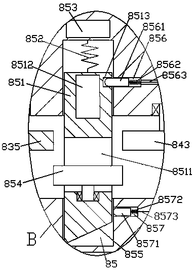
[0029]After clearing is finished, by controlling the drive motor 841 to rotate in reverse, then realize that the first bevel gear 844 drives the second bevel gear 886 and the inner key rotating sleeve 884 to rotate in reverse. At this time, the inner key rotating sleeve 884 drives the second The key shaft 887 and the first key shaft 885 rotate in the opposite direction, and the one-way clutch 8801 on the left side of the second key shaft 887 drives the take-up wheel 888 to rotate, and then the take-up wheel 888 drives the first pulley through the first pull cord 8563. The pin 8561 overcomes the pressing force of the third spring 8562, and makes the first sliding pin 8561 slide toward the right side in the first sliding pin groove 856 until the first sliding pin 8561 is completely disengaged from the connecting groove 8513. At this time, the linkage slider 851 is pulled by the tension spring 852, so that the linkage slider 851 slides to the top position in the linkage slide cavi...

Embodiment 3

[0031] When it is necessary to discharge the cleaning waste liquid, make the piston slider 832 located at the top position in the liquid storage chamber 83, then open the liquid discharge valve 8110, and then power on the electromagnetic coil device 853, and then make the electromagnetic coil device 853 and the magnetic block 8512 generates a repulsive force, and then the linkage slider 851 overcomes the pressing force of the tension spring 852 and slides downward. At this time, the inclined surface 855 at the bottom end of the linkage slider 851 abuts against each other, so that the second sliding pin 8571 overcomes the fourth spring 8572 The pressing force of the second slide pin is retracted into the second sliding pin groove 857, and the second pull cord 8573 is in a relaxed state again. Since the horizontal sliding block 881 is subjected to the pressing force of the second spring 883, the horizontal sliding block 881 is then slid to the horizontal slide groove. The leftmos...


PUM


Abstract

The invention discloses an automobile part ultrasonic washing machine. The automobile part ultrasonic washing machine comprises a washing main body, wherein a washing groove with an opening arranged upwards is formed in the washing main body, an ultrasonic focus cavity is formed in the lower side of the washing groove, an ultrasonic transducer is fixedly arranged on the top wall of the ultrasonicfocus cavity, an ultrasonic generator is fixedly arranged on the bottom wall of the ultrasonic focus cavity, a liquid storage cavity is formed in the left side of the ultrasonic focus cavity, a pistonslide block is connected in the liquid storage cavity in a sliding fit mode, a communication pipe communicating with the washing groove is arranged in the top wall of the liquid storage cavity, multiple groups of washing hairbrushes arranged at equal intervals are arranged in the washing groove, and a hairbrush control mechanism used for controlling the washing hairbrushes to work in a left-rightmovement mode is further arranged in the washing groove. The automobile part ultrasonic washing machine is simple in structure and convenient to operate, and improves overall work efficiency of washing.

Description

technical field [0001] The invention relates to the technical field of parts cleaning, in particular to an ultrasonic cleaning machine for auto parts. Background technique [0002] With the continuous development of the cleaning industry, more and more industries and enterprises have applied ultrasonic cleaning machines. The sound wave propagates in the liquid, so that the liquid and the cleaning tank vibrate together at the ultrasonic frequency. When the liquid and the cleaning tank vibrate, they have their own natural frequency. This vibration frequency is the sound wave frequency, so people hear humming. The principle of the ultrasonic cleaning machine is that the high-frequency oscillation signal sent by the ultrasonic generator is converted into high-frequency mechanical oscillation by the transducer and propagated into the medium-cleaning solvent, and the ultrasonic waves radiate forward in the cleaning liquid, making The liquid flows to produce tens of thousands of t...

Claims


Application Information

Patent Timeline
Patent Type & Authority Applications(China)
IPC IPC(8): B08B3/12B08B1/00
CPCB08B1/008B08B3/12
Inventor 杨桂英
Owner 爱阔特(上海)清洗设备制造有限公司
Why Eureka
Try Eureka