Polishing device for machining shell of environment-friendly exhaust fan

A technology of polishing device and exhaust fan, which is applied in the direction of grinding/polishing safety device, metal processing equipment, grinding/polishing equipment, etc. It can solve the problems of affecting the staff, easy to generate high temperature, low work efficiency, etc., and achieve a scientific structure Reasonable, easy to move, safe and convenient to use

Inactive Publication Date: 2019-12-20
江苏华正数控机械有限公司
View PDF0 Cites 4 Cited by
  • Summary
  • Abstract
  • Description
  • Claims
  • Application Information

AI Technical Summary

Problems solved by technology

[0003] During the processing of the fan casing, in order to ensure the appearance, a layer of paint is usually sprayed on the surface. Before painting, the surface of the casing needs to be polished to ensure the quality of the painting. At the same time, after painting, in order to improve the painting effect, the surface will be polished. In the existing process of polishing the casing, the motor drives the grinding disc to rotate at high speed, and then the surface of the casing is polished and polished. However, during the polishing process, the casing is in contact with the high-speed rotation, which will Large sparks and high-temperature waste chips are generated. The generated sparks not only affect the eyes of the staff, but also the splashed waste chips are easy to injure the staff. Moreover, the motor is prone to high temperature inside under long-term high-speed operation. Long, it is easy to cause damage to the components inside the motor, which in turn leads to damage to the motor, and then makes the work efficiency low. Therefore, in order to solve this series of problems, we propose a polishing device for environmental protection exhaust fan shell processing to solve the problem

Method used


Image

  • Polishing device for machining shell of environment-friendly exhaust fan
  • Polishing device for machining shell of environment-friendly exhaust fan
  • Polishing device for machining shell of environment-friendly exhaust fan

Examples


Embodiment Construction

[0024] The following will clearly and completely describe the technical solutions in the embodiments of the present invention with reference to the accompanying drawings in the embodiments of the present invention. Obviously, the described embodiments are only some, not all, embodiments of the present invention. Based on the embodiments of the present invention, all other embodiments obtained by persons of ordinary skill in the art without making creative efforts belong to the protection scope of the present invention.

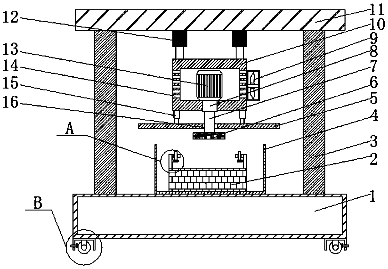
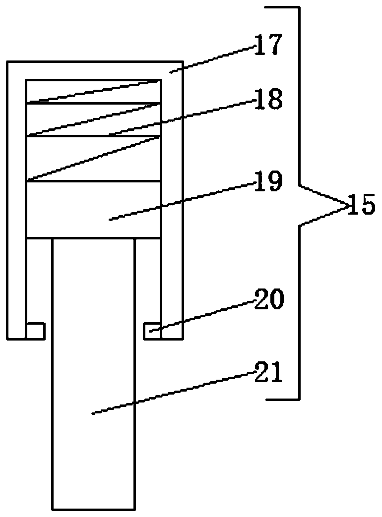
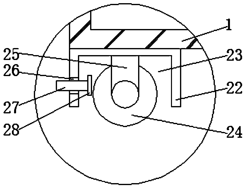
[0025] see Figure 1-5 , the present invention provides a technical solution: a technical solution of a polishing device for environmental protection exhaust fan shell processing, including a base 1, a workbench 2 and a polishing box 4, the polishing box 4 is fixedly installed in the middle of the top of the base 1, and the workbench 2. It is fixedly installed inside the polishing box 4, and the polishing box 4 is an open bottom structure. The four ends of the...


PUM


Abstract

The invention discloses a polishing device for machining a shell of an environment-friendly exhaust fan. The polishing device comprises a base, a workbench and a polishing box. The polishing box is fixedly installed at the middle position of the top of the base, the workbench is fixedly installed inside the polishing box, the polishing box is of a bottom opening structure, the four ends of the topof the base are fixedly provided with supporting columns correspondingly, the top of the base is fixedly provided with a top plate through the four supporting columns, two air cylinders are fixedly installed at the middle position of the bottom of the top plate, an installation box is installed at the bottom of the top plate through the air cylinders, a bearing is arranged at the middle positionof the bottom of the installation box, a driving motor is fixedly installed in the installation box, and a rotating shaft is movably installed at the middle position of the bottom of the installationbox through the bearing. The device has the advantages of being convenient to move and fix and high in safety by arranging a series of structures.

Description

technical field [0001] The invention relates to the technical field of exhaust fan shell processing, in particular to a polishing device for environmental protection exhaust fan shell processing. Background technique [0002] Environmentally friendly exhaust fans refer to fans that can be used as aeration fans in environmentally friendly water treatment aeration systems, and are energy-saving, low-noise, and do not produce secondary environmental pollution. The main products of domestic environmental protection fan manufacturers include large industrial blowers, ventilators, More than 50 series of gas blowers, coke oven blowers, multi-stage high-pressure centrifugal blowers, single-stage high-speed centrifugal blowers, and more than 400 specifications of energy-saving centrifugal fans are widely used in iron and steel smelting, thermal power generation, new dry process cement, Petrochemical, sewage treatment, waste heat recovery, gas recovery and nuclear power and other fiel...

Claims


Application Information

Patent Timeline
Patent Type & Authority Applications(China)
IPC IPC(8): B24B27/00B24B55/02B24B19/00B24B41/06B24B41/02B24B55/06
CPCB24B19/00B24B27/0007B24B27/0046B24B41/02B24B41/06B24B55/02B24B55/06
Inventor 葛昆鹏
Owner 江苏华正数控机械有限公司
Why Eureka
Try Eureka