

Integrated wheel system
A wheel and wheel power technology, which is applied to vehicle components, elastic suspensions, suspensions, etc., can solve the problems of shock absorbers such as limited length, difficulty in popularization, and poor structural strength, and achieve small torque, flexible steering, and good structural strength
- Summary
- Abstract
- Description
- Claims
- Application Information
AI Technical Summary
Problems solved by technology
Method used
Image

Examples
no. 1 example
[0080] The first embodiment is a steering, power, slip integrated wheel.
[0081] Reference to the first embodiment figure 1 , 2 , 3, 4, 5, 6, 7, 8, 9, 10, 11, 12, 13, 13, 14, 17, 20 Instructions.
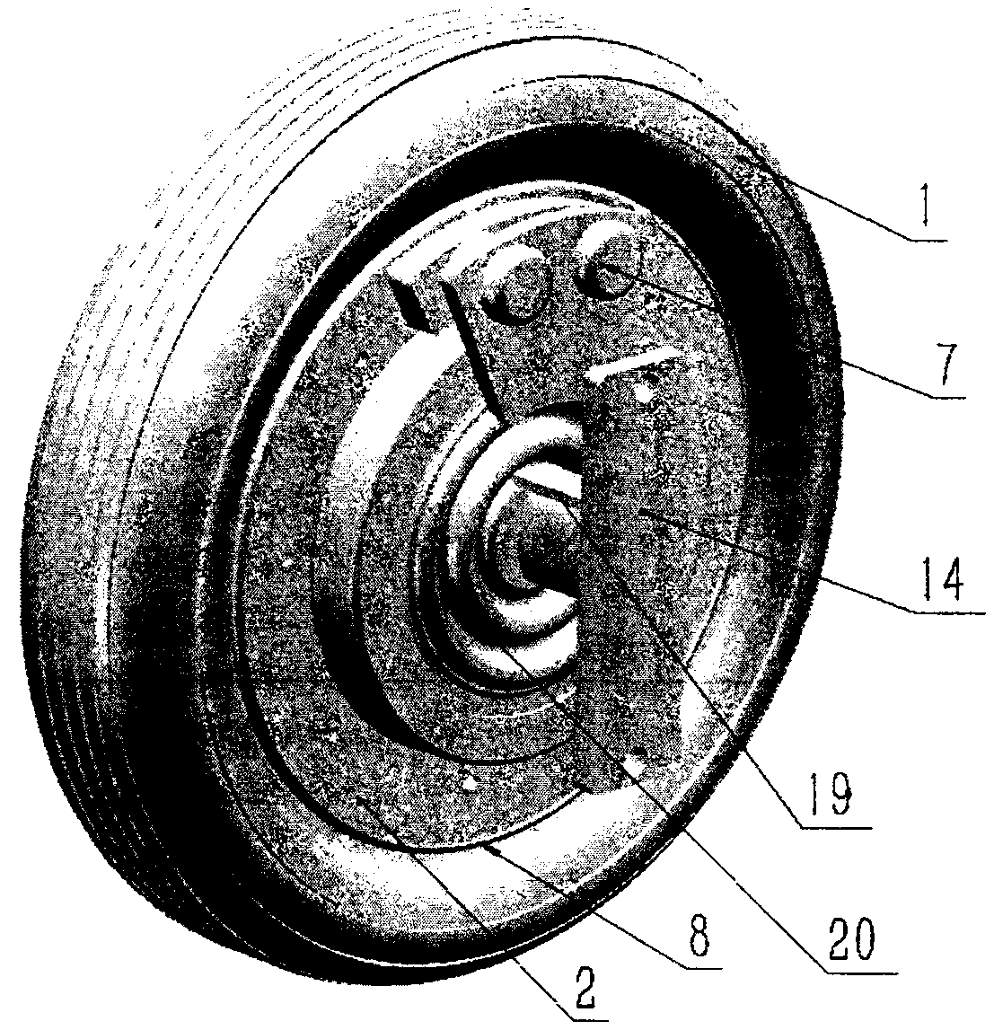
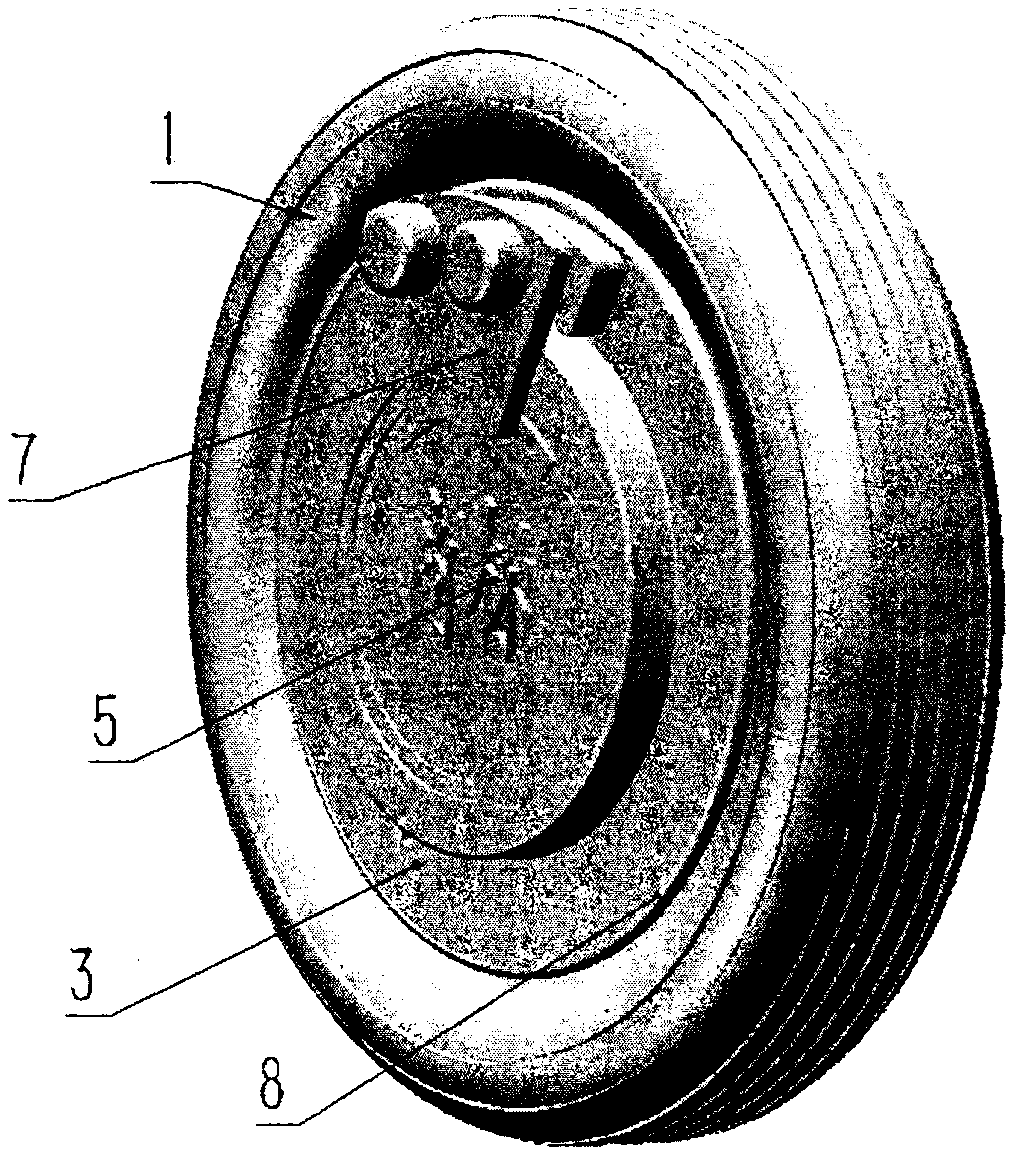
[0082] figure 1 , 2 It is an appearance diagram, and the tire 1 is installed on the rim 8. The left and right hubs 3, 2 are detachably connected to the rim 8 at least one of the left and right sides. The disc brake assembly 7 is arranged on the hub 3,2. The outer middle part of the wheel is sealed with the trademark plate of the shell type main shaft 5, the inner middle part of the wheel is sealed with a rubber seal 20, and the central part stretches out the connecting shaft and the flange of the transverse frame 14 to be connected with the vehicle frame. Middle part stretches out steering arm 19 and is connected with steering gear.
[0083] The appearance of the wheel of the invention is simple, convenient and beautiful.
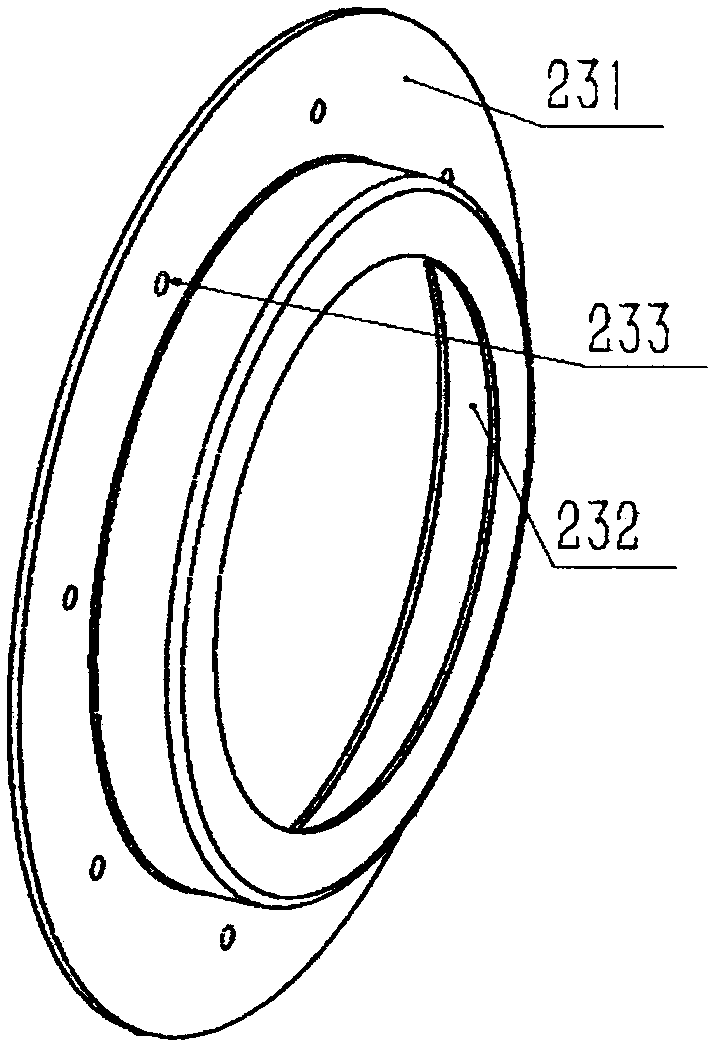
[0084] image 3 It's the left and right hubs. Th...
no. 2 example
[0109] The second embodiment is a sliding, steering integrated wheel.
[0110] The main reference figure of the second embodiment is Figure 19 .
[0111] Most of the existing electric vehicle front wheels are driven without power.
[0112] Simply not installing motor 15, 16 and middle shaft 6, pinion 10, bull gear 11 in the first embodiment is basically the second embodiment. Because the change is too simple and easy to understand, the present invention is not discussed in detail.
[0113] Because the front wheel of the tricycle is a symmetrically supported vehicle frame, the connecting shaft 143 and the flange 144 of the transverse frame 14 are symmetrically arranged in pairs.
no. 3 example
[0115] The third embodiment is power, sliding integrated wheel.
[0116] The rear wheels of the vehicle are generally non-steering.
[0117] The main reference picture of the rear wheel is Figure 16 , 18 Vertical sectional view, its vertical frame 21 is Figure 15 .
[0118] Because there is no steering, so the horizontal frame 14 is not provided in the first embodiment, and the vertical frame 21 is directly connected to the vehicle frame to become the rear wheel.
[0119] The rest are similar to the first embodiment.
[0120] The tire 1 is mounted on the rim 8 . The left and right hubs 3, 2 are detachably connected to the rim 8 at least one of the left and right sides. The disc brake assembly 7 is arranged on the hub 3,2. The outer middle part of the wheel is sealed with the trademark plate of the shell-type main shaft 5, the inner middle part of the wheel is sealed with a rubber seal 20, and the connecting shaft and flange extending from the transverse frame 14 are c...
PUM
 Abstract
Description
Claims
Application Information