
Sewage treatment method

A sewage treatment method and sewage technology, which are applied in water/sewage treatment, biological water/sewage treatment, water/sewage treatment equipment, etc., can solve the problems of affecting the flow rate of sewage treatment, insufficient utilization, and high operating costs, and increase self-efficiency. Aeration capacity, maintenance of biological activity and void variability, low cost effect

Inactive Publication Date: 2019-12-20
佛山市大新农生物技术股份有限公司
View PDF19 Cites 0 Cited by
  • Summary
  • Abstract
  • Description
  • Claims
  • Application Information

AI Technical Summary

Problems solved by technology

[0003] The traditional method uses a single material to be piled up in the box, and the current one includes a bed for sewage treatment. The bed includes an inner treatment chamber for loading sewage, and the inner treatment chamber includes water inlets arranged side by side along the fluid flow direction. Cages and effluent net cages; in the process of sewage treatment, the fluidized bed of water forms a mucous membrane and is easy to coat and form solids, which not only affect the flow rate of sewage treatment, but are also easy to block, slowing down the speed of sewage treatment, and causing sewage to run Filtering and adding additives cannot be fully utilized, so only local aeration with the machine can be used, but the local aeration of the machine requires a long-term air supply from the machine. After the machine is turned on for a long time, not only the utilization rate is low, but also the operating cost is high

Method used


Image

  • Sewage treatment method
  • Sewage treatment method
  • Sewage treatment method

Examples


Embodiment 1

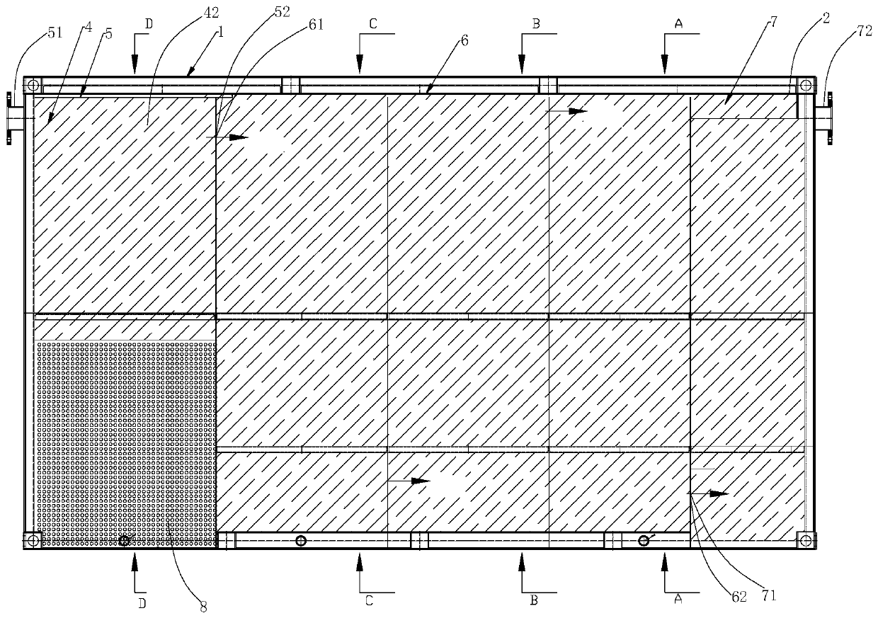
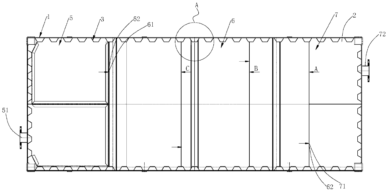
[0043] A method of sewage treatment, such as Figure 1 to Figure 11 As shown, it includes a bed body 1 for sewage treatment, and the bed body 1 includes an inner treatment chamber 19 for loading sewage, and the inner treatment chamber 19 includes water inlet cages 5 arranged side by side along the fluid flow direction, a first transfer Net cage 6, the second transfer net cage 6, the third transfer net cage 6 and the water outlet net cage 7; the water inlet net cage 5 is provided with an aeration layer 4 arranged in the water inlet net cage 5, and the first transfer net cage 6 is provided with the aeration layer 4 arranged in the first transfer net cage 6, the second transfer net cage 6 is provided with the aeration layer 4 arranged in the second transfer net cage 6, and the third transfer net cage 6 Be provided with the aeration layer 4 that is arranged in the third transfer net cage 6, be provided with the aeration layer 4 that is arranged in the water outlet net cage 7 in th...

Embodiment 2

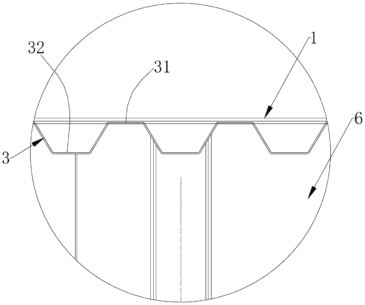
[0056] A fluidized bed for sewage treatment, such as Figure 1 to Figure 11 As shown, a fluidized bed for sewage treatment includes a bed body 1 for sewage treatment. The bed body 1 includes an inner chamber 2 for loading sewage, and the inner chamber 2 is provided with several along the extending direction of the inner chamber 2. The folded portion 3 is concave or convex along the thickness direction of the inner cavity 2 . The folded part 3 includes a concave part 31 or a convex part 32 , the concave part 31 is concave along the thickness direction of the inner cavity 2 , and the convex part 32 is convex along the thickness direction of the inner cavity 2 .

[0057] Such as Figure 1 to Figure 6 As shown, when the water flows through the inner cavity 2 in the bed body 1, the water flow is uniform when the water flows along the inner wall of the inner cavity 2 and the direction of the water flow is to extend along the inner cavity 2. When the water flow reaches the twisted p...

Embodiment 3

[0067] The difference between this embodiment and the first embodiment lies in the arrangement of the recessed portion 31 and the raised portion 32 , and the rest are the same as the first embodiment. In this embodiment, there are at least two protrusions 32 , and the depression 31 is disposed between two adjacent protrusions 32 .


PUM


Abstract

The invention discloses a sewage treatment method, relates to the technical field of sewage treatment and solves the problems that a common machine needs long-term air supply for partial aeration, andthe machine is not only low in utilization rate, but also high in operation cost in long-term operation. According to the technical scheme, the sewage treatment method is characterized by comprisingthe following steps: A, continuously introducing sewage into a water inlet net cage, enabling the sewage to naturally flow through an aeration layer, completing primary self aeration of the sewage, and completing primary filtration treatment; and B, enabling the sewage to flow out from a first water outlet end of the water inlet net cage, enabling the sewage to continuously flow into a water outlet net cage from a third water inlet end, completing secondary self aeration of the sewage, and completing secondary filtration treatment. A self aeration function can be achieved without functions ofa machine but only functions of flowing water in sewage treatment, both the efficiency of long-term sewage treatment can be improved and energy consumption in the sewage treatment process can be reduced, and in addition, the purpose of remarkably improving the aeration capability of an inner cavity can be facilitated.

Description

technical field [0001] The invention relates to the technical field of sewage treatment, in particular to a sewage treatment method. Background technique [0002] With the rapid increase of wastewater discharge, increasingly stringent discharge standards, and the limitation of resource utilization space, stringent requirements are placed on the effectiveness of wastewater treatment process and the capacity of treatment equipment. The research and application of biological fluidized bed treatment of sewage began in the 1970s in the US Environmental Protection Agency. This method combines the relevant technical characteristics of microbial membrane method and fluidized bed, and has large specific surface area, high microbial concentration, high volume loading rate and sludge loading rate, fast mass transfer, strong impact load resistance, and strong purification ability, etc. features. [0003] The traditional method uses a single material to be piled up in the box, and the ...

Claims


Application Information

Patent Timeline
Patent Type & Authority Applications(China)
IPC IPC(8): C02F9/14
CPCC02F1/001C02F3/109C02F3/34C02F2201/007C02F2203/006
Inventor 胡丽红
Owner 佛山市大新农生物技术股份有限公司
Learn More