Novel hanging tool for electroplating of inner wall of oil cylinder

A technology of electroplating racks and oil tanks, which is applied in the direction of electrodes, electrolysis process, electrolysis components, etc. It can solve the problems of difficult and precise installation, increase the difficulty of operation, and difficult installation, so as to improve the efficiency of electroplating, ensure the quality of electroplating, and achieve versatility high effect

Active Publication Date: 2019-12-20
XCMG HYDRAULICS CO LTD
View PDF44 Cites 1 Cited by
  • Summary
  • Abstract
  • Description
  • Claims
  • Application Information

AI Technical Summary

Problems solved by technology

[0005] 1. The existing anode positioning plate is installed separately. Place the anode positioning plate at both ends of the cylinder, and then use several thin iron rods slightly longer than the cylinder to pass through the anode positioning plate, and then fix it. Cylinders of different lengths need Tooling cannot be used universally for different irons;
[0006] 2. The one-by-one installation method is difficult to install. It is difficult to achieve precise installation due to the cooperation of the installers and the proficiency of the operation. It cannot guarantee a good anode positioning ability, and is easily affected by the size of the workpiece, and the conductivity is also poor.
It not only wastes resources but also increases the difficulty of operation, and the installation efficiency of tooling is low;
[0007] 3. When entering the plating tank, the cathode and anode are hoisted separately, and there is eccentricity between the anode and the cylinder, resulting in uneven thickness of the coating

Method used


Image

  • Novel hanging tool for electroplating of inner wall of oil cylinder
  • Novel hanging tool for electroplating of inner wall of oil cylinder
  • Novel hanging tool for electroplating of inner wall of oil cylinder

Examples


Embodiment Construction

[0032] The following is a specific embodiment of the present invention, and the present invention will be further described in conjunction with the accompanying drawings.

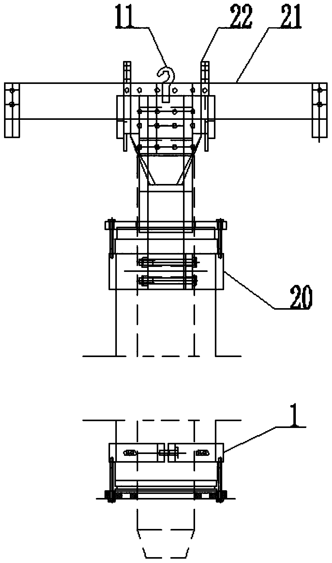
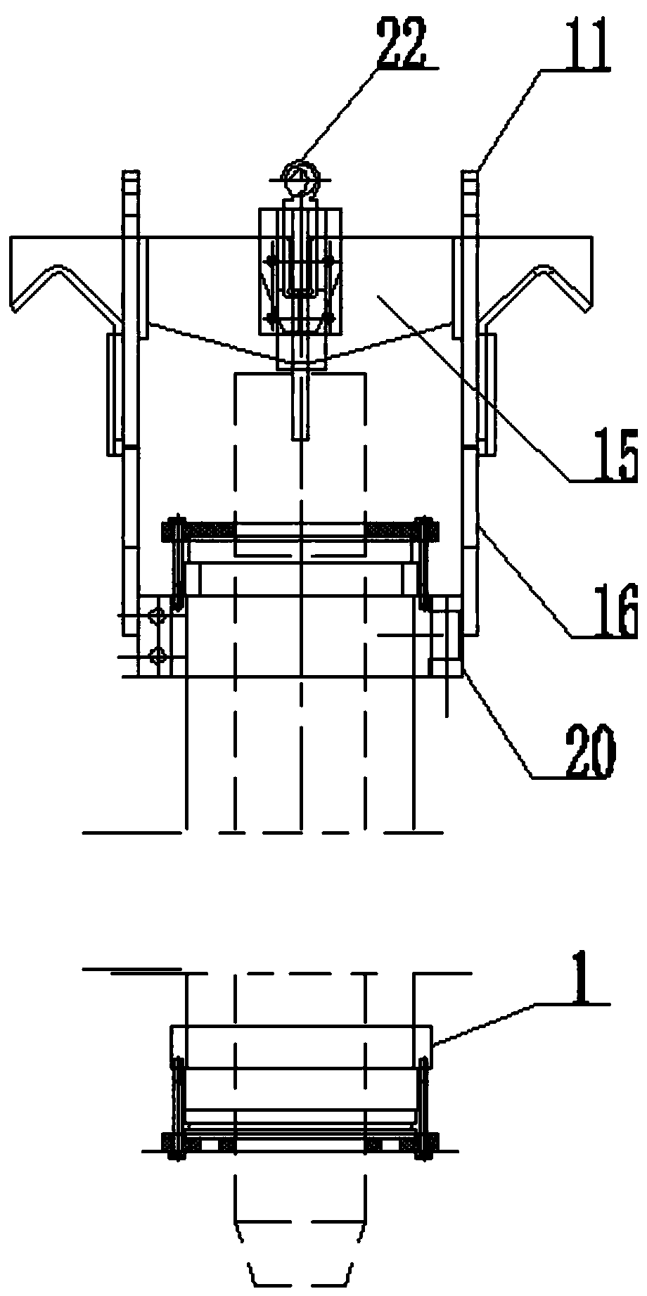
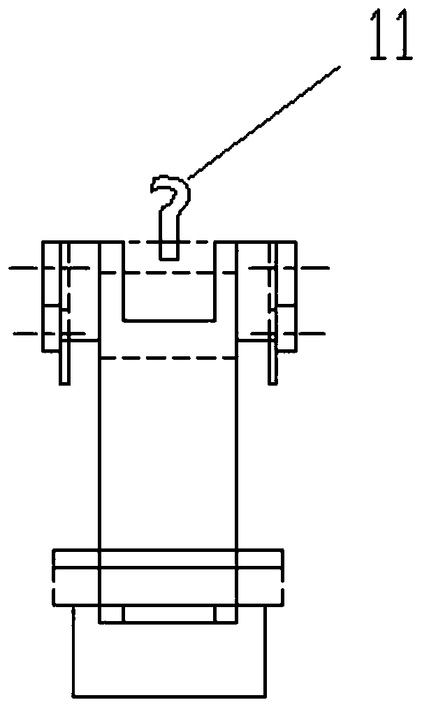
[0033] combine Figure 1 to Figure 4 , Image 6 and Figure 11 As shown, a new type of electroplating hanger for the inner wall of the oil cylinder, the cathode lifting assembly clamps the upper end of the cylinder 9 to be plated, and the cathode lifting assembly is used to connect the upper end of the cylinder 9 to be plated and the cathode conductive device. The anode positioning assembly clamps the lower end of the cylinder 9 to be plated, and the anode positioning assembly is used to connect the lower end of the cylinder 9 to be plated with the anode conductive device. The anode suspension assembly is hung in the bayonet 18 of the cathode suspension assembly, and the anode 23 in the anode suspension assembly passes downward through the cylinder 9 to be coated.

[0034] Anode positioning components: ...


PUM


Abstract

The invention discloses a novel hanging tool for electroplating of the inner wall of an oil cylinder and belongs to the technical field of electroplating. The novel hanging tool comprises a cathode lifting component and an anode positioning component, wherein the cathode lifting component is used for clamping the upper end of a to-be-plated cylinder barrel; the anode positioning component is usedfor clamping the lower end of the to-be-plated cylinder barrel; an anode lifting component is connected to the cathode lifting component in a hanging manner; the cathode lifting component comprises apair of oppositely-arranged vertical plates; each vertical plate is connected with a cathode lifting hook; the outer side of each vertical plate is fixedly provided with a V-shaped hook; the two vertical plates are fixedly connected with each other by a pair of middle plates; the two middle plates are provided with clamping openings which face to each other; and the lower ends of the two verticalplates are each fixedly connected with a cathode clamping ring which is used for clamping the upper end of the to-be-plated cylinder barrel. According to the novel hanging tool disclosed by the invention, the anode lifting component, the anode positioning component and the cathode lifting component are combined mutually so that the components are simplified, the original complicated structure is broken, an integrated tool is realized, quick installation and integrated lifting are realized, the electroplating efficiency is improved, and the electroplating quality is guaranteed.

Description

technical field [0001] The invention relates to the technical field of electroplating, in particular to a novel electroplating hanger for the inner wall of an oil cylinder, which is suitable for the electroplating process for the inner wall of a hydraulic oil cylinder. Background technique [0002] Electroplating is the process of plating a thin layer of other metals or alloys on the surface of certain metals using the principle of electrolysis. It is a process of using electrolysis to attach a layer of metal film to the surface of metal or other materials, so as to prevent metal Oxidation (such as rust), improve wear resistance, electrical conductivity, reflective properties, corrosion resistance (copper sulfate, etc.) and enhance the appearance. [0003] According to the shape of the parts, the technical requirements of the coating, the electroplating process and the size of the equipment, there are different types of hangers. For example, there is a difference between au...

Claims


Application Information

Patent Timeline
Patent Type & Authority Applications(China)
IPC IPC(8): C25D17/08C25D17/10
CPCC25D17/08C25D17/10
Inventor 于铁柱陈登民韦金钰盛红瑞
Owner XCMG HYDRAULICS CO LTD
Why Eureka
Try Eureka