Comprehensive pipe gallery co-constructed with riverside green tunnel as revetment retaining wall

A technology of comprehensive pipe gallery and retaining wall, which is applied in the direction of buildings, piers, and walls, can solve the problems of large excavation depth, dry season of rivers, ecological damage, etc., and achieve the goal of saving engineering costs and saving engineering investment Effect

Pending Publication Date: 2019-12-20
WUHAN MUNICIPAL ENG DESIGN & RES INST
View PDF0 Cites 5 Cited by
  • Summary
  • Abstract
  • Description
  • Claims
  • Application Information

AI Technical Summary

Problems solved by technology

[0004] River revetments, riverside greenways, and comprehensive pipe corridors are all linear projects along the river. In order to avoid redundant construction and save investment, they should be jointly constructed and implemented simultaneously as much as possible. However, there are few reports on such projects.
[0005] In addition, many comprehensive utility corridors built along rivers still have relatively large defects: since the buried depth of most comprehensive utility corridors is in the range of 5m to 8m, and the excavation depth is relatively large, it is often necessary to use steel cement-soil mixing walls or drill holes Cast-in-situ piles, etc. for foundation pit support
If a deep foundation pit is excavated by this support method next to the river bank, the anti-seepage wall will inevitably block the supply channel of the river and groundwater, which will easily cause the river to dry up in the dry season, and the groundwater cannot be conserved in the wet season, making it difficult to repair ecological damage

Method used


Image

  • Comprehensive pipe gallery co-constructed with riverside green tunnel as revetment retaining wall
  • Comprehensive pipe gallery co-constructed with riverside green tunnel as revetment retaining wall
  • Comprehensive pipe gallery co-constructed with riverside green tunnel as revetment retaining wall

Examples


Embodiment Construction

[0042]The principles and features of the present invention are described below in conjunction with the accompanying drawings, and the examples given are only used to explain the present invention, and are not intended to limit the scope of the present invention.

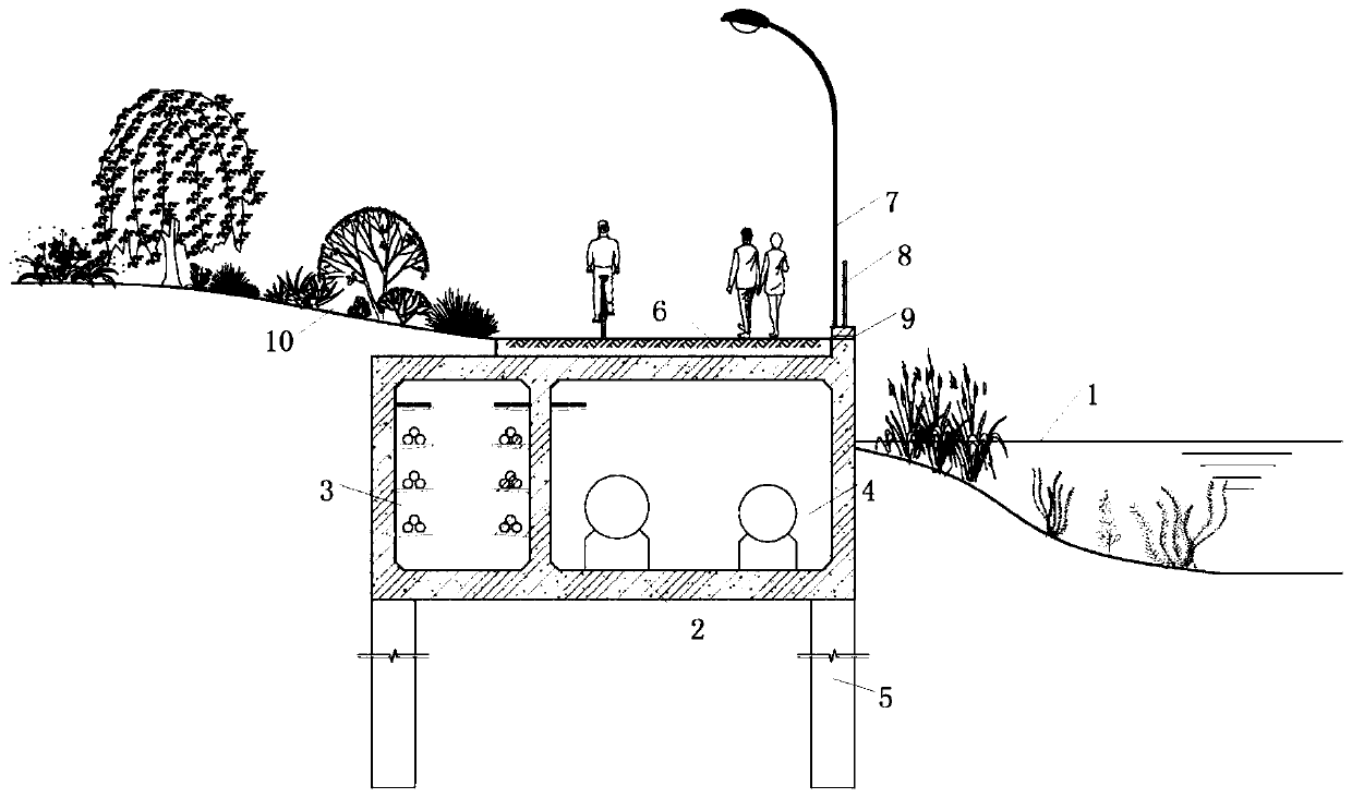
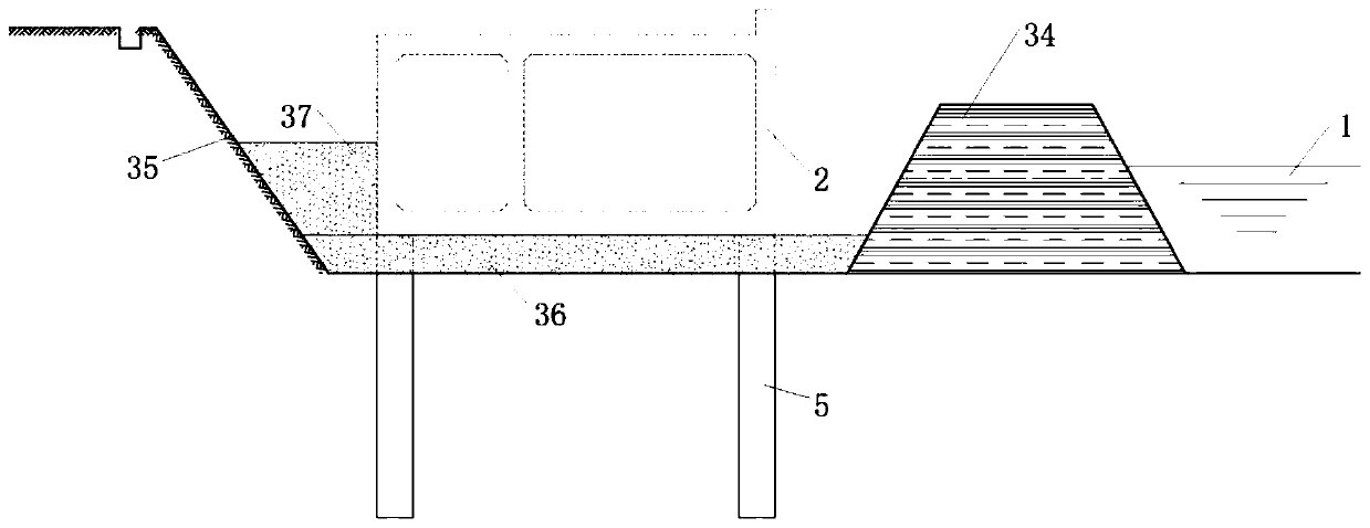
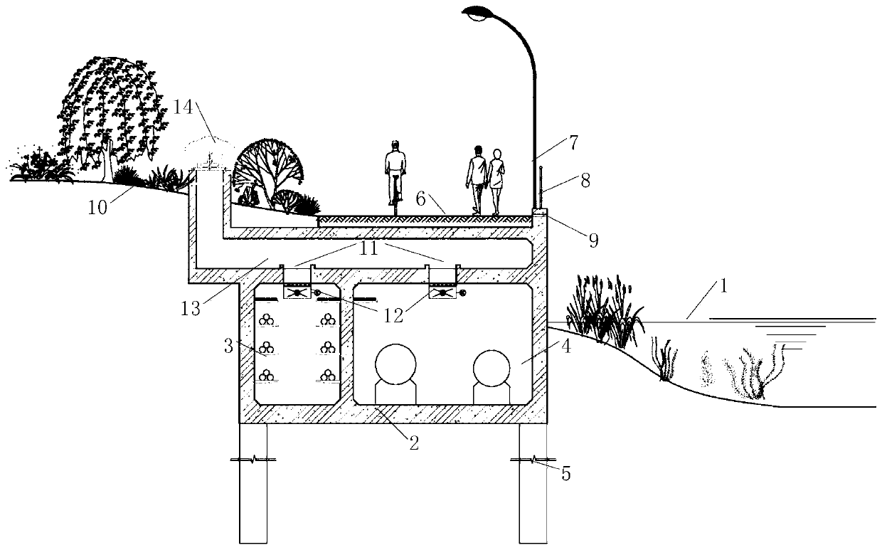
[0043] Such as figure 1 and figure 2 As shown in the figure, a comprehensive pipe gallery is built together with the riverside greenway and serves as the revetment retaining wall, including the comprehensive pipe gallery 2 set between the river channel 1 and the river bank green buffer zone 10 (the interior of the comprehensive pipe gallery 2 is hollow to form a cabin) One side wall of the comprehensive pipe gallery 2 faces the water, and the other side wall supports the bank slope soil mass of the river bank green buffer zone 10, and a riverside greenway 6 is provided on the top of the roof of the comprehensive pipe gallery 2, so The lower part of the bottom plate of the comprehensive pipe gallery 2 is fixed and b...


PUM


Abstract

The invention relates to a comprehensive pipe gallery co-constructed with a riverside green tunnel as a revetment retaining wall. The comprehensive pipe gallery comprises a comprehensive pipe gallerybody which is arranged between a river channel and a riverside greening buffer zone, wherein the riverside green tunnel is arranged at the upper part of a top plate of the comprehensive pipe gallery body, and the lower part of a bottom plate of the comprehensive pipe gallery body is fixedly buried in a soil layer through uplift piles and anti-slide piles; the lower part of the bottom plate of thecomprehensive pipe gallery body is provided with a permeable underlayer, and medium coarse sand fills a fertilizer groove of a foundation pit in one side, close to the bank, of the permeable underlayer. According to the comprehensive pipe gallery, the revetment retaining walls, the river green tunnel and the comprehensive pipe gallery are synchronously constructed in a combined manner, so that limited bank slope space is intensively utilized, repeated construction is avoided, and engineering investment is saved; the comprehensive pipe gallery is shallow except part of nodes, so that permanentwater-stop facilities such as water-stop curtains and the like are avoided when deep foundation pits are excavated; and the cushion layer of the comprehensive pipe gallery and the backfill region of the foundation pit fertilizer tank have high permeability, so that the smoothness of a channel for mutually supplying river water and underground water is ensured, and the construction concept of sponge cities is met.

Description

technical field [0001] The invention relates to the technical field of urban underground comprehensive pipe gallery design, in particular to a comprehensive pipe gallery which is built together with a riverside greenway and serves as a revetment retaining wall. Background technique [0002] Urban inland rivers are not only important flood control and drainage channels, but also have important ecological and landscape values. In recent years, the development of cities has put forward higher requirements for improving the flood control and drainage capacity and landscape quality of rivers. Many cities have carried out comprehensive renovation of related rivers: on the one hand, dredging, widening, and building revetments to increase the flow capacity of the river; Water-friendly landscape areas and greenways, etc. [0003] As a naturally formed long and narrow space, urban inland rivers often become corridors for trunk pipelines such as high-voltage power overhead lines. In...

Claims


Application Information

Patent Timeline
Patent Type & Authority Applications(China)
IPC IPC(8): E02D29/045E02B3/06
CPCE02B3/066E02D29/10
Inventor 龚哲唐琳强何小林兰迪王翔张戎杨卫星彭定新杨泉鑫何亦真刘长庚张妮娜
Owner WUHAN MUNICIPAL ENG DESIGN & RES INST
Why Eureka
Try Eureka