
Anchoring-type hydraulic casing shaping tool

A fixed and hydraulic technology, applied in wellbore/well components, earth-moving drilling, etc., can solve the problems of low power motor power, unable to continue the mining work, stratum dislocation and collapse, etc., to achieve the effect of tight connection

Pending Publication Date: 2019-12-20
海塔石油科技有限公司
View PDF0 Cites 3 Cited by
  • Summary
  • Abstract
  • Description
  • Claims
  • Application Information

AI Technical Summary

Problems solved by technology

[0002] In the process of oil and gas development, oil and gas wells are caused by stratum dislocation and subsidence due to long-term stratum exploitation, resulting in distortion and deformation of oil layer casing, making subsequent exploitation work impossible, and even causing oil and gas wells to be scrapped, resulting in serious economic losses
Therefore, it is necessary to reshape the casing. The traditional method of overhauling the reshaping method has high operating costs and a long construction period, which brings inconvenience to production and construction.
[0003] The existing casing shaping tools have the following problems: 1. The mechanical shaping tools need to be pressurized and rotated, and the drilling pressure and torque applied by the minor repair equipment are limited, which cannot meet the process requirements; 2. The mechanical shaping tools produce large torques, and the power motor The power is relatively small, which cannot meet the shaping requirements; 3. The force and shock force are large, and the effect of casing shaping cannot be guaranteed

Method used


Image

  • Anchoring-type hydraulic casing shaping tool
  • Anchoring-type hydraulic casing shaping tool
  • Anchoring-type hydraulic casing shaping tool

Examples


Embodiment 1

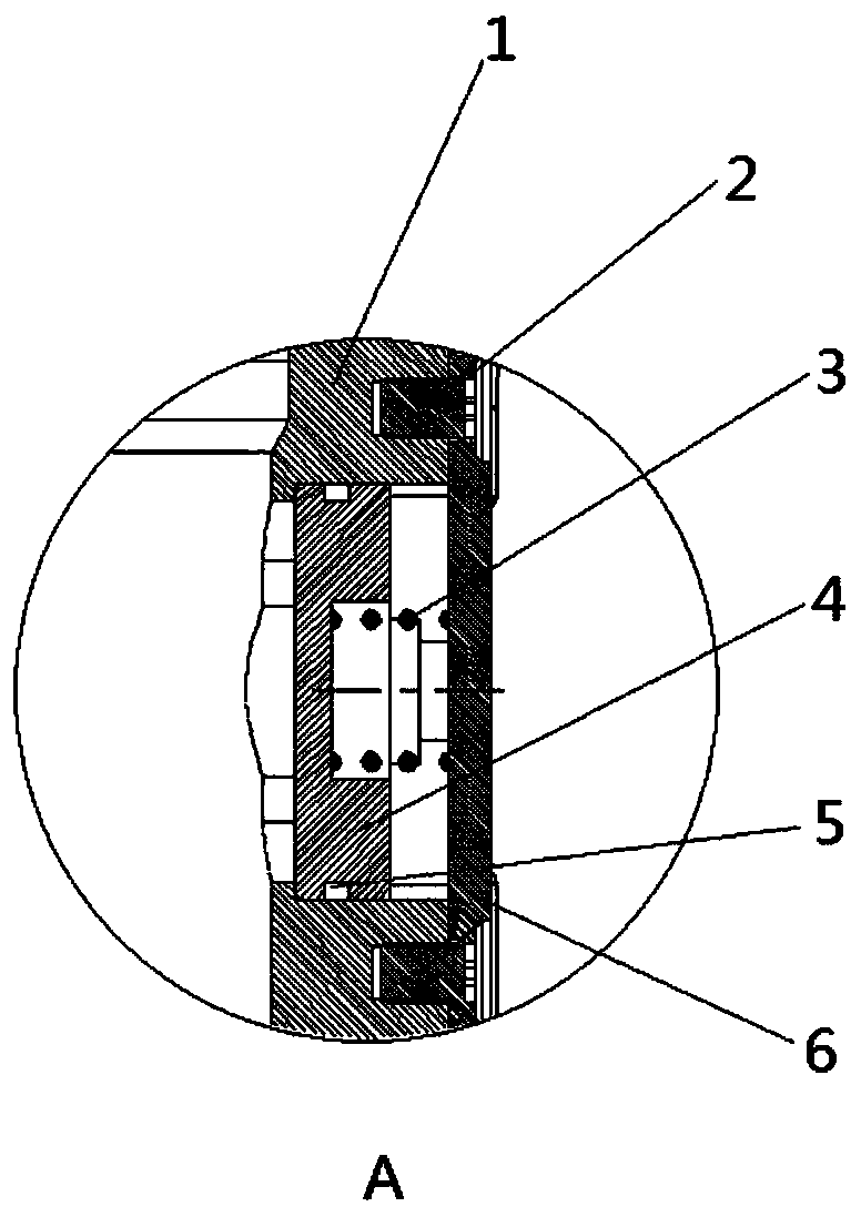
[0023] see Figure 1~6, in an embodiment of the present invention, an anchored hydraulic casing shaping tool includes an anchor body 1, an internal thread 1 is provided on the inner wall of the anchor body 1, and the anchor body 1 can be connected to an external oil pipe through the internal thread 1, The outer wall of the anchor body 1 is provided with a plurality of fluke holes, the plurality of fluke holes are provided with flukes 4, the inside of the fluke 4 is provided with a return spring 3, and the anchor body 1 is also fixed A pressure plate 6 is connected, and the connection mode between the pressure plate 6 and the anchor body 1 is not limited. In this embodiment, preferably, the pressure plate 6 and the anchor body 1 are fixedly connected by a plurality of fixing pins 2, and the The pressure plate 6 has a fixing effect on the return spring 3 and a limiting effect on the anchor fluke 4. The outer wall of the lower end of the anchor body 1 is provided with an upper jo...

Embodiment 2

[0027] In order to make the connection between the various components in the anchored hydraulic casing shaping tool more tightly, this embodiment makes the following improvements on the basis of embodiment 1. The improvements are: the outer wall of the anchor fluke 4 is connected to the A sealing ring 1 is arranged between the anchor holes of the outer wall of the body 1, and a sealing ring 2 8 is arranged between the outer wall of the lower end of the upper joint 7 and the inner wall of the upper end of the upper hydraulic cylinder 11, and the outer wall of the upper end of the upper piston 10 is connected to the inner wall of the upper hydraulic cylinder. 11, a sealing ring 3 9 is arranged between the inner walls of the upper end, and a plurality of sealing rings 4 12 are arranged between the outer wall of the lower end of the upper piston 10 and the inner wall of the lower end of the upper hydraulic cylinder 11. In this embodiment, preferably, the sealing ring 4 The number o...


PUM


Abstract

The invention discloses an anchoring-type hydraulic casing shaping tool. The upper end of the anchoring-type hydraulic casing shaping tool is connected with an oil pipe through a pipe thread. When theanchoring-type hydraulic casing shaping tool is tripped in and encounters resistance, pressurization is conducted through a ground pump truck, high-pressure liquid enters the anchoring-type hydrauliccasing shaping tool through the oil pipe and flows through first liquid inlet channels in the lower ends of anchor jaws, anchor jaw compression reset springs expand outwards under the effect of the pressure to be anchored on the inner wall of a casing, a supporting rod moves downwards to compress a shaping spring, and a baffle ring has a protection function; the supporting rod continues to move downwards, and balls expand downwards under the effect of shaping grooves in the outer wall of the supporting rod; when a shaping shaft and a lower guide sleeve pass through a shaping position, the pressure of the oil pipe is released, the anchor jaws retreat under the effect of the reset springs, the supporting rod moves upwards, and the balls enter the shaping grooves again; and a first sealing ring, a second sealing ring, a third sealing ring, a fourth sealing ring, a fifth sealing ring, a sixth sealing ring, a seventh sealing ring, an eighth sealing ring, a ninth sealing ring and a tenth sealing ring are arranged.

Description

technical field [0001] The invention relates to an oil field mechanical equipment, in particular to an anchor type hydraulic casing shaping tool. Background technique [0002] In the process of oil and gas development, oil and gas wells are caused by stratum dislocation and subsidence due to long-term stratum exploitation, resulting in the distortion and deformation of the oil layer casing, making the follow-up exploitation work impossible, and even causing the scrapping of oil and gas wells, causing serious economic losses. Therefore, it is necessary to reshape the casing. The traditional method of overhauling the reshaping method has high operating costs and a long construction period, which brings inconvenience to production and construction. [0003] The existing casing shaping tools have the following problems: 1. The mechanical shaping tools need to be pressurized and rotated, and the drilling pressure and torque applied by the minor repair equipment are limited, which...

Claims


Application Information

Patent Timeline
Patent Type & Authority Applications(China)
IPC IPC(8): E21B29/10
CPCE21B29/10
Inventor 商延兵李洪波徐传斌耿辉
Owner 海塔石油科技有限公司
Learn More