Camshaft unit and method for producing a camshaft unit

A technology of camshaft and camshaft adjuster, which is applied in the direction of camshaft drive, engine components, engine sealing, etc. It can solve the problems of unidentifiable, seal damage, hydraulic fluid leakage, etc., and achieve the effect of long life

Active Publication Date: 2019-12-20
ECO HLDG 1 GMBH
View PDF28 Cites 0 Cited by
  • Summary
  • Abstract
  • Description
  • Claims
  • Application Information

AI Technical Summary

Problems solved by technology

As a result, seal damage can result
Tilting and damage to the seals involves the danger that a perceptible leakage of hydraulic fluid occurs only after a longer load phas

Method used


Image

  • Camshaft unit and method for producing a camshaft unit
  • Camshaft unit and method for producing a camshaft unit
  • Camshaft unit and method for producing a camshaft unit

Examples


Embodiment Construction

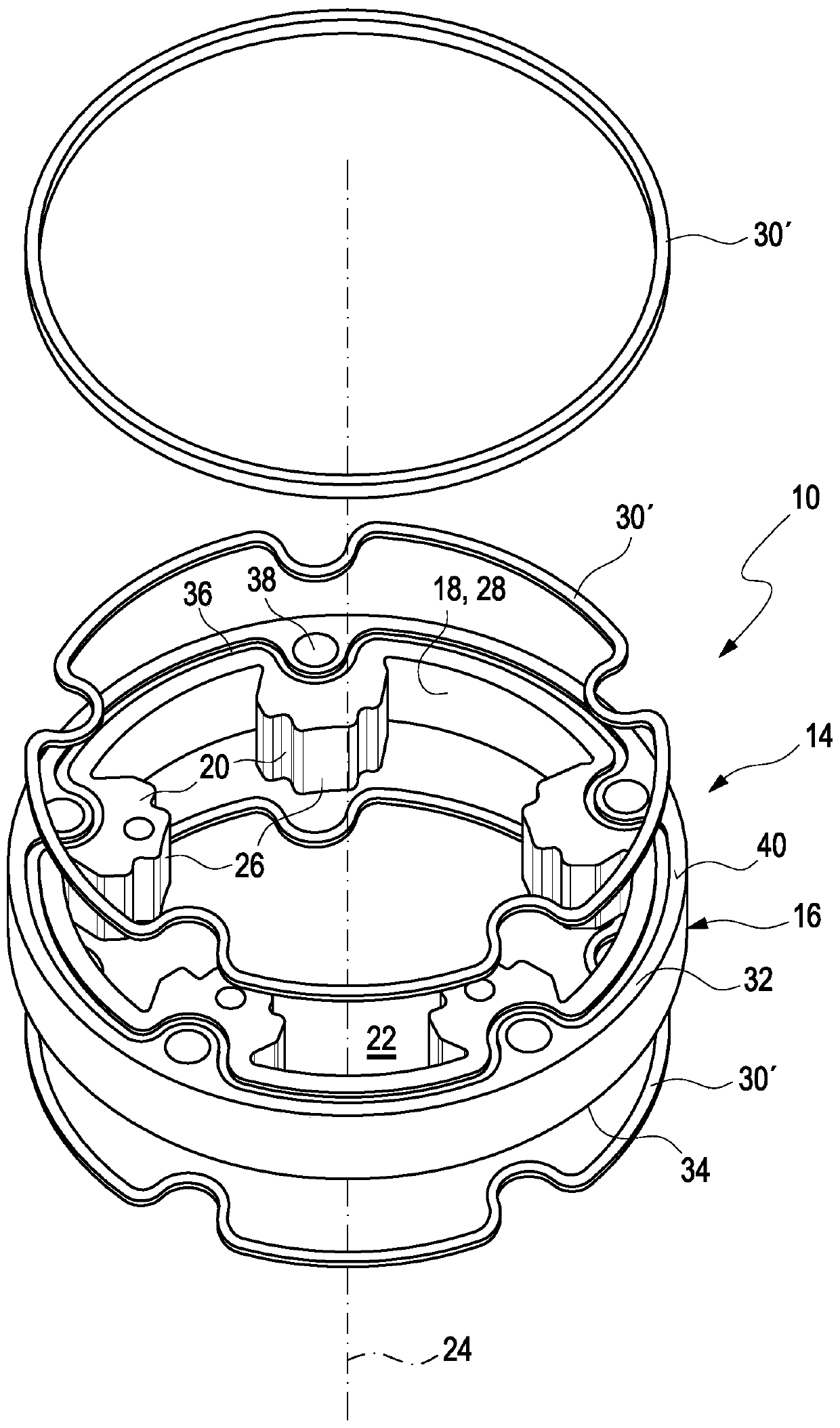
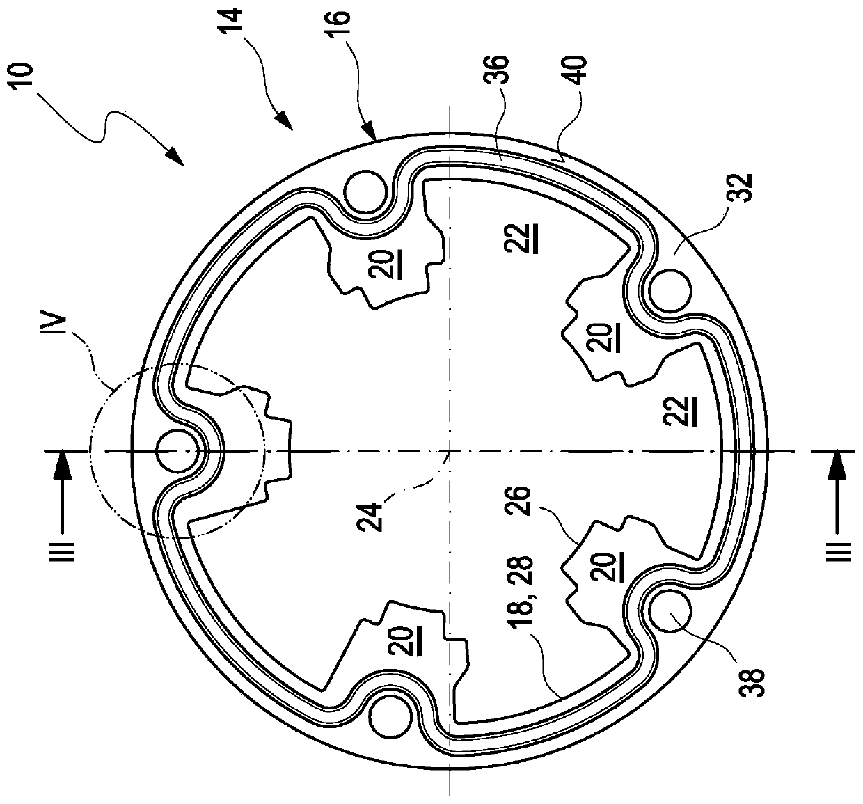
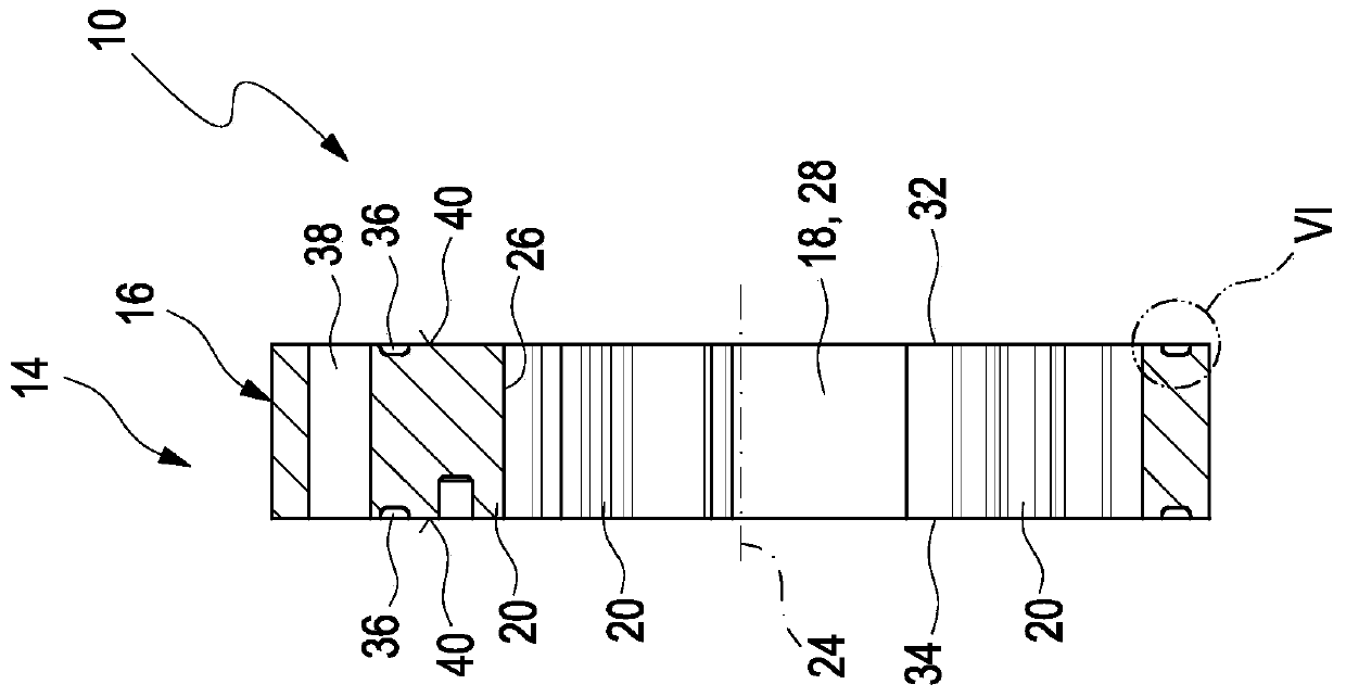
[0027] A camshaft unit 10 constructed according to the prior art is constructed in the form of a camshaft adjuster whose stator 14 is constructed according to FIG. 1 . The camshaft adjuster 10 can bring about a change in the opening and closing times of the gas exchange valves of the internal combustion engine during the operation of the internal combustion engine (not shown in detail).

[0028] FIG. 9 shows a further prior art camshaft adjuster 10 in an exploded view. This shows by way of example a typical construction of a camshaft adjuster 1 , wherein the invention is not, however, restricted to this construction.

[0029] For this purpose, the relative angular position of a camshaft (not shown in detail) of the internal combustion engine relative to a crankshaft (not shown in detail) of the internal combustion engine is continuously varied by means of a camshaft adjuster 10 , the camshaft being twisted relative to the crankshaft. The opening and closing times of the gas e...


PUM


Abstract

The invention relates to a camshaft unit having at least a first component (14) and a second component, the first component (14) having a first sealing surface (40) and the second component having a second sealing surface; the two sealing surfaces (40) mutually are arranged opposite one another, wherein a sealing element (30) is formed between the two sealing surfaces (40). According to the invention, the sealing element (30) can be applied to at least one of the sealing surfaces (40) in the liquid state and is hardenable before the two components (14) are assembled, and a final shape of the sealing element can be achieved by means of the assembly of the two components (14). Furthermore, the invention relates to a method for producing a camshaft unit.

Description

technical field [0001] The invention relates to a camshaft unit and a method for producing a camshaft unit. Background technique [0002] Camshaft units for internal combustion engines are known. A camshaft unit basically refers to a camshaft of an internal combustion engine for controlling the intake valves and exhaust valves of the internal combustion engine, a camshaft adjuster for changing the position of the camshaft relative to the crankshaft of the internal combustion engine and generally belonging to camshaft adjusters for Operates the actuator of the camshaft adjuster. The camshaft unit has hydraulic fluid and is at least sealed from the environment, so that the hydraulic fluid flowing through the camshaft unit remains in the provided fluid circuit, which does not have to be closed forcibly. Depending on the design of the camshaft unit, sealing within the camshaft unit may likewise be required. In other words, a structural component or component is to be sealed r...

Claims


Application Information

Patent Timeline
IPC IPC(8): F01L1/047B29C69/00
CPCB29C69/00F01L1/047F01L1/3442F01L2001/34456F01L2001/34469F01L2001/34479F01L2250/02F01L2250/04F16J15/10F01L2303/00
Inventor 比约恩·雅各布森格哈德·布鲁姆阿克谢尔·拉克内维尔纳·哈伯斯菲利普·伦德
Owner ECO HLDG 1 GMBH
Why Eureka
Try Eureka