Intelligent electric actuator of flow monitoring valve

An electric actuator and flow monitoring technology, applied in the direction of valve operation/release device, valve details, valve device, etc., can solve the problems of valve failure, cumbersome assembly, alarm and so on

Pending Publication Date: 2019-12-20
ZHEJIANG SCI-TECH UNIV
View PDF1 Cites 7 Cited by
  • Summary
  • Abstract
  • Description
  • Claims
  • Application Information

AI Technical Summary

Problems solved by technology

[0003] Most of the current electric actuators simply control the valve opening, and can control the valve position to be fully open or fully closed, but they cannot effectively control the flow value in the pipeline, that is, they cannot automatically adjust the valve opening according to the flow rate. Spend
At the same time, it does not have the function of wireless communication and closed-loop adjustment control.
[0004] Obtaining flow data needs to rely on flow meters and other related equipment, resulting in complex overall structure of the equipment, bulky, cumbersome assembly, and flow meter data and actuator data cannot constitute effective data interaction, which is also a defect
[0005] There is also a lack of corresponding fault monitoring equipment in actual engineering applications. When a fault or abnormality occurs in the fluid delivery system, the valve cannot give a timely alarm, and it is impossible to know the exact location of the fault in the pipeline. It can only be eliminated by manual inspection, which costs a lot of money Manpower and material resources and low efficiency
[0006] The data related to the fluid in the pipeline cannot be stored and analyzed, and the temperature of the fluid cannot be known, so some accidents that could have been avoided cannot be avoided, causing major economic losses
Secondly, the staff cannot remotely and wirelessly control the valve opening and perform cloud data interaction

Method used


Image

  • Intelligent electric actuator of flow monitoring valve
  • Intelligent electric actuator of flow monitoring valve
  • Intelligent electric actuator of flow monitoring valve

Examples


Embodiment Construction

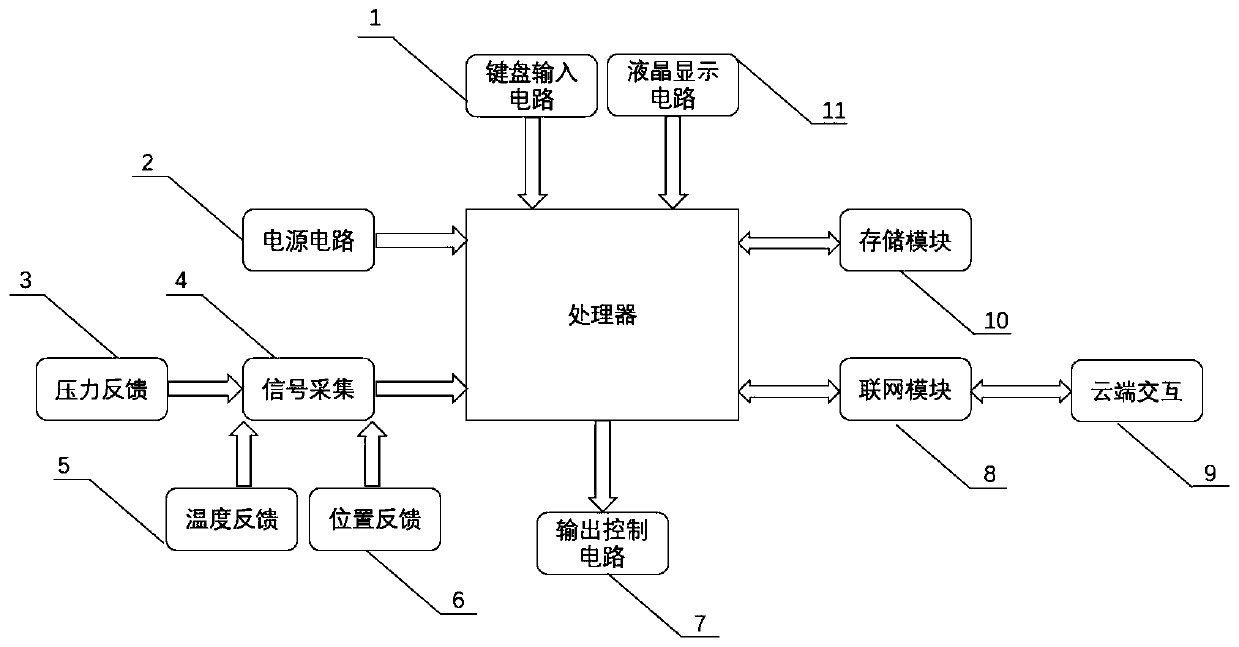
[0029] Specific embodiments of the present invention such as Figure 1-4 Shown is a monitoring electric actuator for an intelligent flow valve, which includes an electric execution unit 16, a control unit, a signal acquisition unit, a human-computer interaction unit 17, a storage unit 10, a cloud interaction unit 9 and a power supply unit 2. The control unit is controlled by a technician Purchasing the processor MCU on the market according to the conventional requirements, the processor MCU is connected with the electric execution unit 16 through the output control circuit 7; when the output control circuit 7 interacts with the processor for data, the communication protocol adopts the MODBUS protocol, and the communication data needs to pass through the CRC of both parties check. Specifically, the MODBUS protocol card adopts a two-wire half-duplex RS485 interface, which can be configured to identify bus parameters such as baud rate, device address, and parity bit. Among them,...


PUM


Abstract

The invention discloses an intelligent electric actuator of a flow monitoring valve. The intelligent electric actuator comprises an electric actuating unit, an angular displacement sensor, a pressuresensor, a temperature sensor, a man-machine interaction unit, a cloud side interaction unit, a storage unit and a power source unit. The electric actuating unit is used for rotating the valve, and theangular displacement sensor is used for acquiring the precise position of the current valve. The pressure sensor is used for acquiring the upstream and downstream pressure value data of the valve. The temperature sensor is used for acquiring the temperature of fluid in a pipeline. The man-machine interaction module is used for allowing a user to be in data communication with the equipment. The storage module is used for storing historical flow information, historical fault information and historical temperature information. The power source module is used for supplying power to normal work ofthe whole system and all modules. The intelligent electric actuator can achieve a lot of practical functions, such as flow monitoring, flow regulation and control, fault prediction, fault alarming and remote data interaction, and the whole system accords with the actual application scenarios and historical background of intellectualization, automation and Internet of Things.

Description

technical field [0001] The invention belongs to the technical field of valves, in particular to an intelligent electric actuator for flow monitoring valves. Background technique [0002] The valve is a control component in the fluid delivery system, which has functions such as cut-off, adjustment, flow diversion, reverse flow prevention, pressure stabilization, flow diversion or overflow pressure relief. The actuator is the main part of the control valve. It can be used to control the rotation angle of the valve to control the corresponding valve opening, so as to control the air, water, steam, various corrosive media, mud, oil, etc. in the pipeline. The purpose of flow of various types of fluids such as liquid metals and radioactive media. [0003] Most of the current electric actuators simply control the valve opening, and can control the valve position to be fully open or fully closed, but they cannot effectively control the flow value in the pipeline, that is, they cann...

Claims


Application Information

Patent Timeline
Patent Type & Authority Applications(China)
IPC IPC(8): F16K31/02F16K37/00
CPCF16K31/02F16K37/005
Inventor 金玉珍张宸宇王凯林哲
Owner ZHEJIANG SCI-TECH UNIV
Why Eureka
Try Eureka