Supercharge Your Innovation With Domain-Expert AI Agents!

Motor vehicle blind area detection method and system

A detection method and detection system technology, applied in computer parts, image enhancement, image analysis and other directions, can solve the problems of difficult expansion, affect detection accuracy, poor detection efficiency, etc., to achieve easy expansion, improve detection accuracy, and simple steps. Effect

Pending Publication Date: 2019-12-20
SHENZHEN LONGHORN AUTOMOTIVE ELECTRONICS EQUIPCO
View PDF6 Cites 0 Cited by
  • Summary
  • Abstract
  • Description
  • Claims
  • Application Information

AI Technical Summary

Problems solved by technology

[0002] The current blind spot detection system of motor vehicles adopts ranging methods and can be roughly divided into radar technology and vision technology. Radar technology uses millimeter-wave radar to detect distance by sending and receiving ultrasonic waves, but this method has limitations and is not easy to expand. , the versatility is very poor; and the distance measurement method of vision technology generally uses the camera behind the motor vehicle to shoot to obtain the rear image of the vehicle, and calculates the distance between the vehicles through the known internal parameters of the camera and the installation height and angle. Therefore, the detection efficiency In addition, the error of this distance measurement method will become more and more obvious as the distance between motor vehicles increases, and when the camera angle changes, the measurement distance will also be inaccurate. Obviously, the above two methods Both are prone to large errors, which affect the detection accuracy and cannot detect dangerous moving targets in real time.

Method used


Image

  • Motor vehicle blind area detection method and system
  • Motor vehicle blind area detection method and system
  • Motor vehicle blind area detection method and system

Examples


Embodiment Construction

[0060] The present application will be described in further detail below in conjunction with the accompanying drawings and specific embodiments. It should be understood that the following exemplary embodiments and descriptions are only used to explain the present invention, not as a limitation to the present invention, and, in the case of no conflict, the embodiments in the application and the features in the embodiments can be combined with each other .

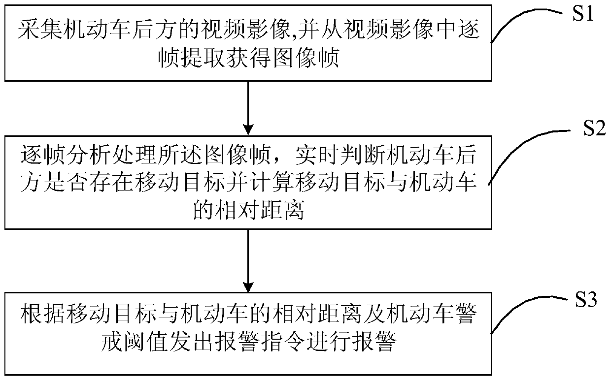
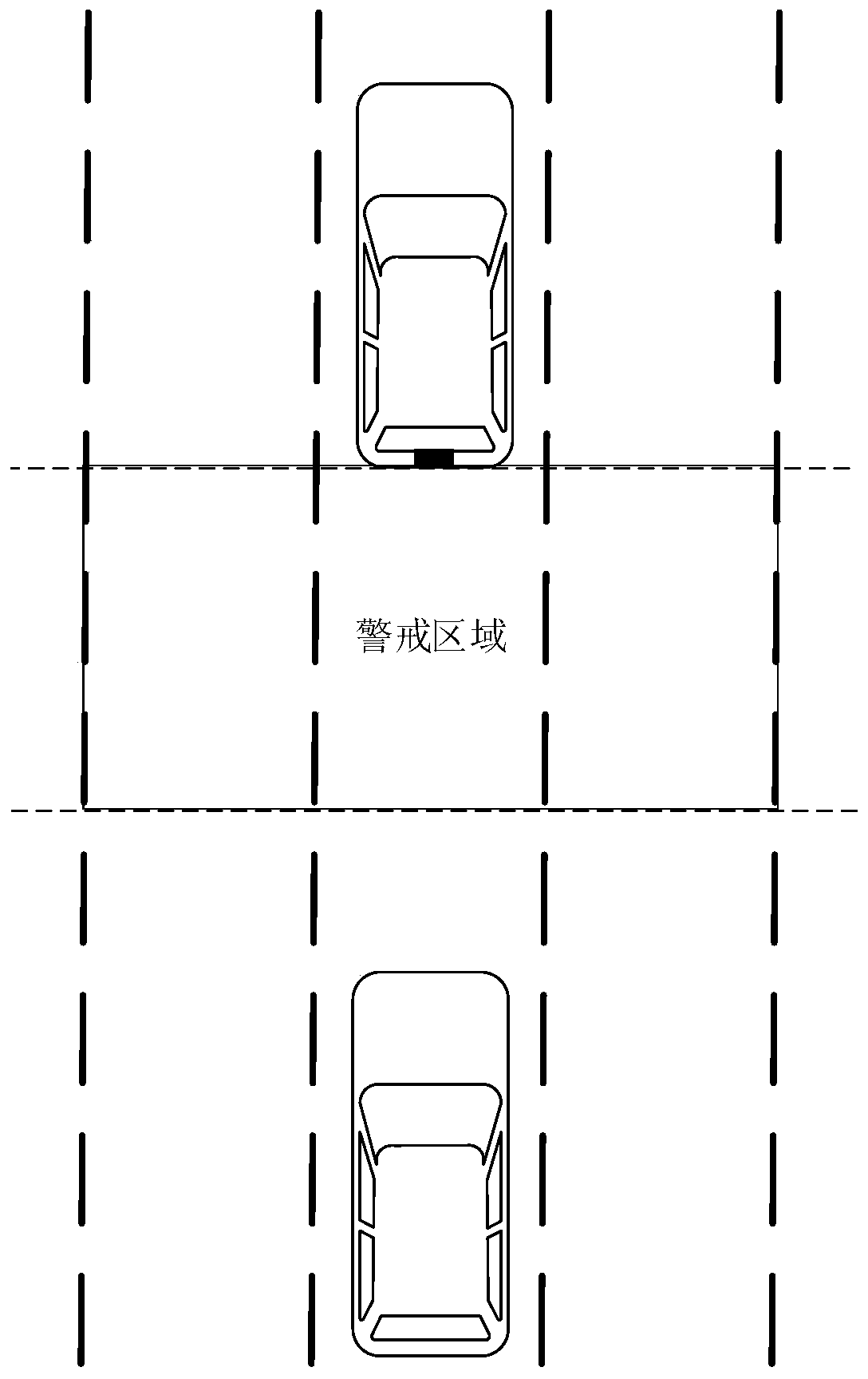
[0061] Such as Figure 1 to Figure 2 As shown, the embodiment of the present invention firstly provides a method for detecting a blind spot of a motor vehicle, comprising the following steps:

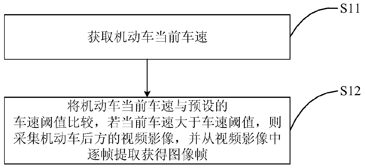
[0062] S1: Collect video images behind the motor vehicle, and extract image frames from the video images frame by frame;

[0063]S2: analyzing and processing the image frames frame by frame, judging in real time whether there is a moving target behind the motor vehicle and calculating the relative distance between the moving target ...


PUM


Abstract

The embodiment of the invention provides a motor vehicle blind area detection method and system, and the method comprises the following steps: collecting a video image behind a motor vehicle, and extracting image frames from the video image frame by frame; the image frames are analyzed and processed frame by frame, judging whether a moving target exists behind the motor vehicle or not in real time, and calculating the relative distance between the moving target and the motor vehicle; and sending an alarm instruction to give an alarm according to the relative distance between the moving targetand the motor vehicle and the motor vehicle warning threshold. According to the embodiment of the invention, whether the moving target exists behind the motor vehicle is judged by analyzing the imageframes of the images behind the motor vehicle frame by frame, and the relative distance between the moving target and the motor vehicle is calculated, so that whether the moving target is dangerous isjudged, the steps are very simple, and the dangerous moving target can be detected in real time for reference of a driver.

Description

technical field [0001] Embodiments of the present invention relate to the field of detection of blind spots of motor vehicles, in particular to a method and system for detecting blind spots of motor vehicles. Background technique [0002] The current blind spot detection system of motor vehicles adopts ranging methods and can be roughly divided into radar technology and vision technology. Radar technology uses millimeter-wave radar to detect distance by sending and receiving ultrasonic waves, but this method has limitations and is not easy to expand. , the versatility is very poor; and the distance measurement method of vision technology generally uses the camera behind the motor vehicle to shoot to obtain the rear image of the vehicle, and calculates the distance between the vehicles through the known internal parameters of the camera and the installation height and angle. Therefore, the detection efficiency In addition, the error of this distance measurement method will be...

Claims


Application Information

Patent Timeline
IPC IPC(8): G06K9/00G06K9/32G06T5/00G06T5/40G06T7/269B60Q9/00
CPCG06T7/269G06T5/40B60Q9/00G06T2207/10016G06V20/40G06V20/56G06V10/25G06V2201/07G06T5/70
Inventor 岳莹莹刘克会
Owner SHENZHEN LONGHORN AUTOMOTIVE ELECTRONICS EQUIPCO
Features
  • R&D
  • Intellectual Property
  • Life Sciences
  • Materials
  • Tech Scout
  • Unparalleled Data Quality
  • Higher Quality Content
  • 60% Fewer Hallucinations
Learn More