
General repair method for cable damage

A repair method and technology for cable damage, applied in the direction of insulation/armored cable repair equipment, etc., can solve the problems of high repair cost, troublesome operation, electrical corrosion of materials, etc., and achieve the effect of wide application range, convenient operation and firm combination

Inactive Publication Date: 2019-12-20
SOUTHWEST JIAOTONG UNIV
View PDF5 Cites 10 Cited by
  • Summary
  • Abstract
  • Description
  • Claims
  • Application Information

AI Technical Summary

Problems solved by technology

[0003] There are three main situations of local cable damage: one is "water tree" damage failure, the cable is served in a humid environment, and there are defects or impurities on the surface or interface of the conductor, and moisture gathers under the action of the electric field, making the insulation layer of the cable and "Tree-trunk" damage to the sheath layer, resulting in a significant drop in insulation resistance at the cable damage
The second is "electric tree" damage. The cable is served in a dry environment, and the insulation layer and the sheath layer are locally uneven or subject to external interference, resulting in high electromagnetic shock, and the material produces electrical corrosion, showing polarization, fatigue and Rapid aging due to thermal effects, forming trunk-type damage to the insulation layer and sheath layer, which in turn leads to partial insulation failure of the cable
The third is "mechanical damage". The cable is served in a dry environment, and its insulation layer is subjected to mechanical external force during use, resulting in local mechanical damage, resulting in partial insulation failure of the cable.
The structure of the device is complicated, and when the damaged part is obviously larger than the distribution interval (radian) of the liquid outlet, the one-time repair of the damaged part cannot be realized, and it needs to be re-aligned, and two or more repair operations are required. The operation is cumbersome, and the repair high cost
When the area of ​​the continuous loss part of the cable is large and deep, the lifting distance of the clamping claws is large, the repair filling space becomes smaller, the repair thickness of the cable is reduced, and the repair quality is poor
[0007] In summary, there are three reasons for insulation failure. The existing repair methods use different methods according to different types (causes) of cable insulation failure. It is impossible to use one method to uniformly repair the three insulation failure types; and each repair There are insurmountable flaws in both methods

Method used


Image

  • General repair method for cable damage
  • General repair method for cable damage
  • General repair method for cable damage

Examples


Embodiment 1

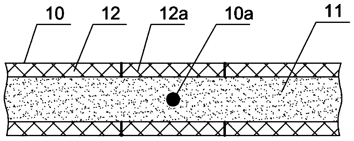
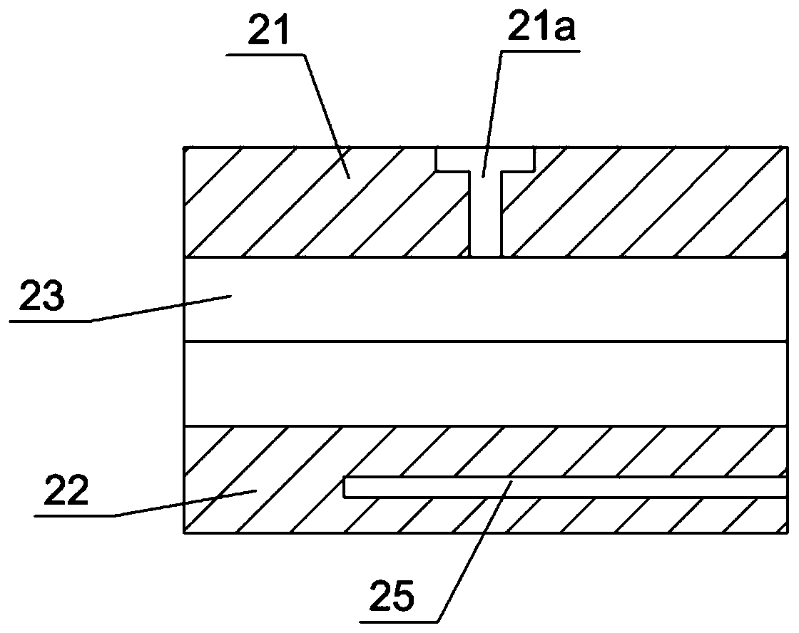
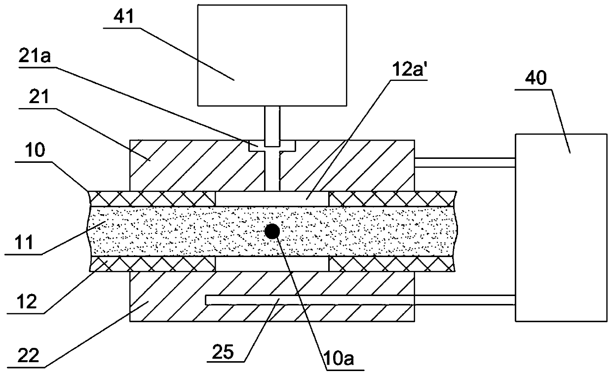
[0058] Figure 1-3 It shows that the first specific implementation of the present invention is: a general repair method for cable damage, the cable 10 is composed of a conductor 11 in the center and an insulating layer 12 outside the conductor 11; the general repair method, the steps of which are:

[0059] A. Removal of insulation damage section

[0060] Use a leakage detector to measure the center position and length of the insulation damage section 12a where the insulation damage part of the cable 10 is located, and record the center position as the repair center 10a of the cable, and then remove the insulation damage section 12a to form an insulation repair gap 12a ', get the cable 10 with the insulation damaged section removed;

[0061] B. Selection of insulation layer repair mold

[0062] Select the insulating layer repair mold that is made of upper mold base 21, lower mold base 22 for use, form circular through-hole 23 between described upper mold base 21, lower mold ...

Embodiment 2

[0069] figure 1 , 4 , 5 show that the second embodiment of the present invention is basically the same as the method of Example 1, the difference is only: the two ends of the circular through hole 23 of the selected insulating layer repair mold are also provided with a diameter larger than the insulating layer. Large via hole 24 of layer 12 diameter.

Embodiment 3

[0071] Figure 6-10 It shows that the third specific implementation of the present invention is: a general repair method for cable damage, the cable 10 is composed of a central conductor 11, an insulating layer 12 outside the conductor 11, and a sheath outside the insulating layer 12. Cover layer 13 is formed; Described general restoration method, its steps are:

[0072] a. Removal of insulation damage section and sheath layer

[0073] Use a leakage detector to measure the center position and length of the insulation damage section 12a where the insulation damage part of the cable 10 is located, and record the center position as the repair center 10a of the cable, and then remove the sheath layer 13 outside the insulation damage section 12a , the removed sheath layer is recorded as the removed sheath section 13a, and then the insulation damage section 12a is removed to form an insulation repair gap 12a'; and the length of the removed sheath section 13a is greater than the len...


PUM


Abstract

The invention discloses a general repair method for cable damage. The method mainly comprises a step of removing an insulation damage section, namely forming an annular insulation repair notch to obtain a cable without the insulation damage section, a step of selecting an insulating layer repairing mold, wherein the diameter of a circular through hole of the mold is equal to that of an insulatinglayer, and the length is larger than that of an insulation damage section, a step of repair the insulating layer, namely placing a cable in the insulating layer repair mold, and enabling the center ofthe insulation damage section to coincide with a center of a middle section through hole of the mold, and a step of starting a mold temperature controller and an injection molding machine to carry out injection molding on the insulation repair notch to obtain a repaired cable. According to the method, various cable insulation damages can be repaired, a repairing material can reach a fine and island-type defect part, the repairing material and an existing insulating layer of the cable are fully melted, the combination is good, the thickness of a repairing layer is consistent and uniform, and the repairing quality is good.

Description

technical field [0001] The invention relates to a method for repairing cable damage. Background technique [0002] The cable consists of a conductor, an insulating layer, or a conductor, an insulating layer, and a sheath layer, and is the basic element for transmitting power. When cable damage leads to insulation failure, it will affect the safety and reliability of power transmission. When local damage to the cable causes local insulation failure, and the overall life of the cable is long, replacing the cable as a whole will lead to an unnecessary increase in power transmission costs. Therefore, it is usually used after repairing it. [0003] There are three main situations of local cable damage: one is "water tree" damage failure, the cable is served in a humid environment, and there are defects or impurities on the surface or interface of the conductor, and moisture gathers under the action of the electric field, making the insulation layer of the cable and The sheath ...

Claims


Application Information

Patent Timeline
IPC IPC(8): H02G1/16
CPCH02G1/16
Inventor 赵永翔孙亚洲刘志伟丁春嵘吕崇伟闫楚良
Owner SOUTHWEST JIAOTONG UNIV
Learn More