Supercharge Your Innovation With Domain-Expert AI Agents!

Robot shutdown charging pile structure

A technology of charging piles and robots, which is applied in the direction of current collectors, electric vehicles, electrical components, etc., can solve the problems of squeezing charging piles, short strokes of micro switches, and sparks, so as to reduce friction, improve safety, and reduce The effect of resistance

Pending Publication Date: 2019-12-20
HANGZHOU AMY RONOTICS CO LTD
View PDF0 Cites 2 Cited by
  • Summary
  • Abstract
  • Description
  • Claims
  • Application Information

AI Technical Summary

Problems solved by technology

[0002] The existing robot charging pile is controlled by a micro switch, but the stroke of the micro switch is short. When the micro switch of the robot chassis touches the slope of the charging pile and reaches the trigger stroke of the micro switch, the robot starts to stop, but due to Inertia, the robot is still moving backwards, resulting in a dangerous situation of squeezing the charging pile
At the same time, after long-term use, the mechanical device of the micro switch on the chassis is easily damaged. When the robot retreats again, the micro switch fails and the robot cannot stop, because the robot retreats horizontally and the charging pile electrode moves up and down. During the contact process between the two, the electrode sheet of the charging pile will cause greater resistance to the robot chassis, because the robot retreats at a low speed, which will cause the robot to be unable to climb the charging pile. At the same time, the electrode sheet of the charging pile is a A cylinder with a circular arc on the upper end. When the robot is recharging, when the electrode sheet of the charging pile slides into the bottom of the robot and contacts the electrode sheet of the chassis, due to the surface contact, there will be friction during the interaction process. The resistance is large and only suitable for small ones such as sweepers. For robots with charging current, for service robots that require high current for charging, because of the high current, it will cause sparks, resulting in blackening of the pole piece after a long time, decreased conductivity, and low surface contact charging efficiency

Method used


Image

  • Robot shutdown charging pile structure
  • Robot shutdown charging pile structure
  • Robot shutdown charging pile structure

Examples


Embodiment Construction

[0037] The following will clearly and completely describe the technical solutions in the embodiments of the present invention with reference to the accompanying drawings in the embodiments of the present invention. Obviously, the described embodiments are only some, not all, embodiments of the present invention.

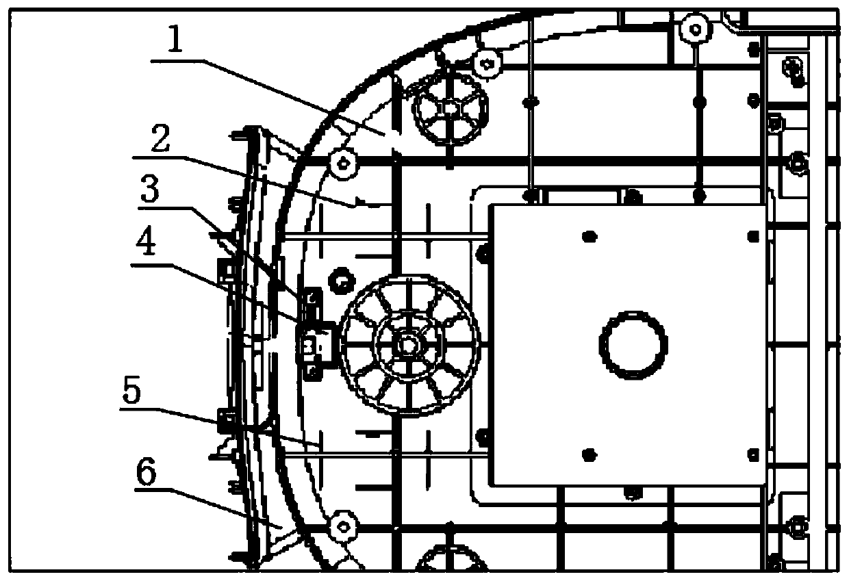
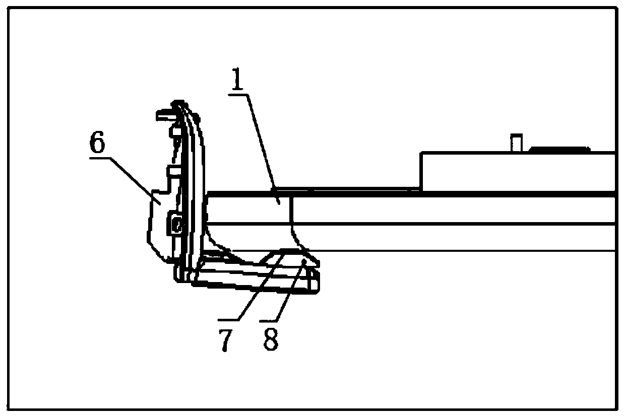
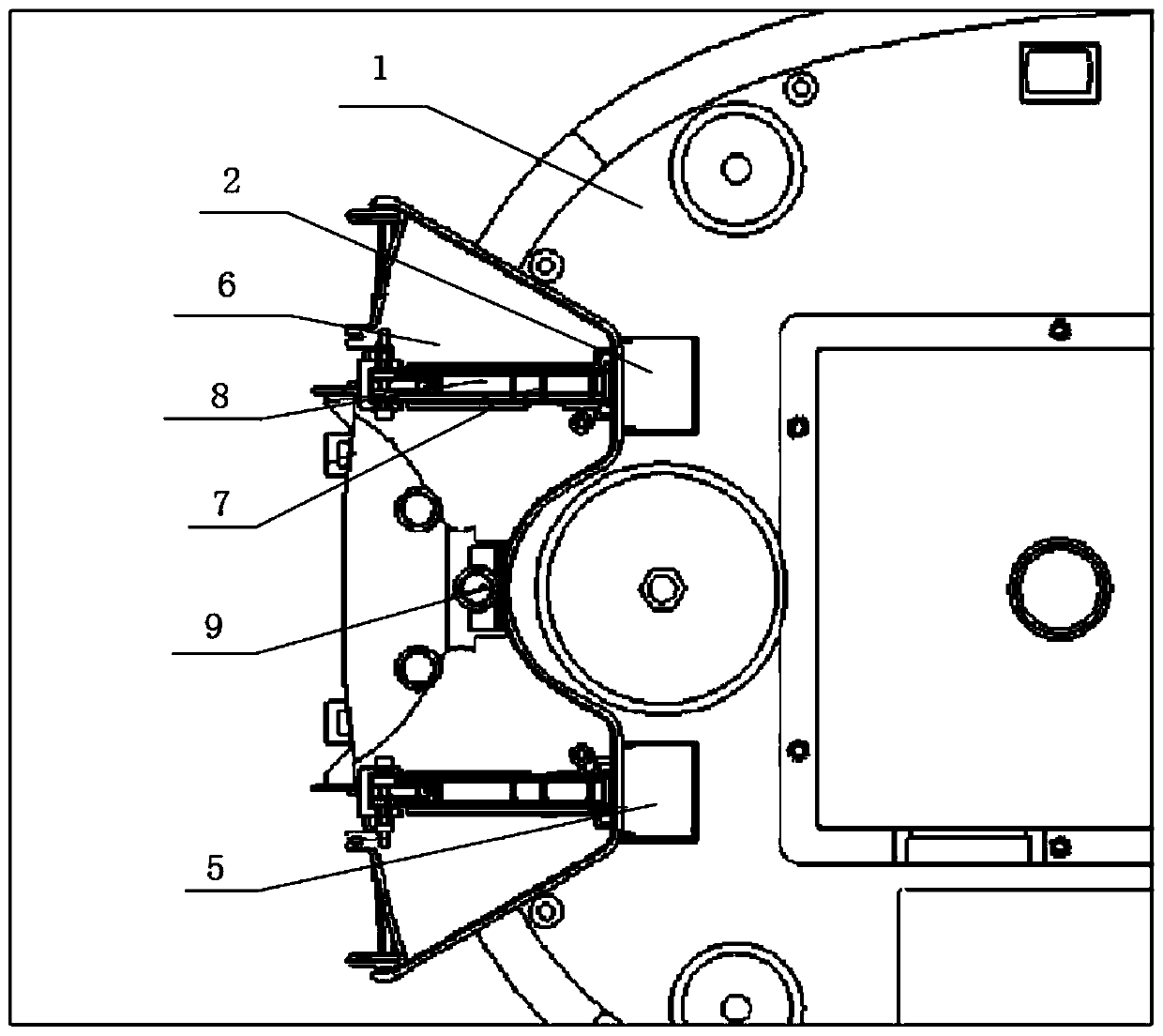
[0038] Such as Figure 1-5 As shown, a robot shutdown charging pile structure, including the robot 1, the charging pile 6 and the charging pile shrapnel 8:

[0039] A first chassis charging pole piece 2 and a second chassis charging pole piece 5 are installed at the tail end of the chassis of the robot 1, and a Hall sensor 4 is installed through a mounting bracket 3 at the middle position of the chassis tail of the robot 1;

[0040] The center of the front cover of the charging pile 6 is equipped with a magnet 9 for induction with the Hall sensor 4;

[0041] The charging pile shrapnel 8 is rotatably connected to the front bottom of the charging pile 6 through the co...


PUM


Abstract

The invention discloses a robot shutdown charging pile structure. The structure comprises a robot, a charging pile and a charging pile elastic plate, wherein a first chassis charging pole plate and asecond chassis charging pole plate are installed at a tail end of a chassis of the robot. In the recharging process, when a magnet is detected through a Hall sensor, the robot decelerates to stop, thestroke of a magnet induced by the Hall sensor is long, a charging pile is not squeezed by the robot, moreover, mechanical triggering of a microswitch is avoided, a phenomenon of mechanical trigger failure after long-time use is avoided, so long-time reliable use can be realized, a robot electrode plate and a charging pile electrode plate are in good contact, then a wireless signal is emitted to inform the charging pile to turn on a power supply, the first chassis charging electrode plate and the second chassis charging electrode plate of the robot are in contact with a charging pile electrodeplate firstly and then are electrified, so sparks are not generated, and charging safety is improved.

Description

technical field [0001] The invention relates to the technical field of robot charging piles, in particular to a structure of a charging pile when a robot stops. Background technique [0002] The existing robot charging pile is controlled by a micro switch, but the stroke of the micro switch is short. When the micro switch of the robot chassis touches the slope of the charging pile and reaches the trigger stroke of the micro switch, the robot starts to stop, but due to Inertia, the robot is still moving backwards, resulting in a dangerous situation of squeezing the charging pile. At the same time, after long-term use, the mechanical device of the micro switch on the chassis is easily damaged. When the robot retreats again, the micro switch fails and the robot cannot stop, because the robot retreats horizontally and the charging pile electrode moves up and down. During the contact process between the two, the electrode sheet of the charging pile will cause greater resistance ...

Claims


Application Information

Patent Timeline
IPC IPC(8): H02J7/00
CPCH02J7/0042
Inventor 伍文飞
Owner HANGZHOU AMY RONOTICS CO LTD
Features
  • R&D
  • Intellectual Property
  • Life Sciences
  • Materials
  • Tech Scout
  • Unparalleled Data Quality
  • Higher Quality Content
  • 60% Fewer Hallucinations
Learn More