Piezoelectric microphone chip and piezoelectric microphone

A microphone and piezoelectric technology, applied in the direction of piezoelectric devices/electrostrictive devices, piezoelectric/electrostrictive transducer microphones, piezoelectric/electrostrictive/magnetostrictive devices, etc., can solve the sensitivity problem Demand and other issues, to achieve the effect of improving S/N and high yield

Active Publication Date: 2019-12-20
FUJIFILM CORP
View PDF10 Cites 6 Cited by
  • Summary
  • Abstract
  • Description
  • Claims
  • Application Information

AI Technical Summary

Problems solved by technology

Therefore, further sensitivity requirements cannot be accommodated

Method used


Image

  • Piezoelectric microphone chip and piezoelectric microphone
  • Piezoelectric microphone chip and piezoelectric microphone
  • Piezoelectric microphone chip and piezoelectric microphone

Examples


Embodiment

[0097] Hereinafter, the present invention will be described in more detail with examples and comparative examples given.

[0098] Microphones of Examples 1 to 4 and Comparative Examples 1 to 3 were produced.

[0099] Figure 11 The dimensions of one spacer and the definitions of the dimensions of a plurality of piezoelectric conversion parts (second electrodes) provided on one spacer in the piezoelectric microphone chips of the examples and comparative examples are shown in . Here, the piezoelectric conversion part a provided in the central part is provided 2 and the four outer piezoelectric conversion parts a arranged around it 11 ~a 14 .

[0100] Let the x-direction length of the separator 51 be Ld x , set the length in the y direction as Ld y . will move toward the central piezoelectric transducer a 2 The x-direction length of is set to Lin x , set the y-direction length to Lin y . In addition, in each example, the piezoelectric conversion part a 2 The region is...


PUM


Abstract

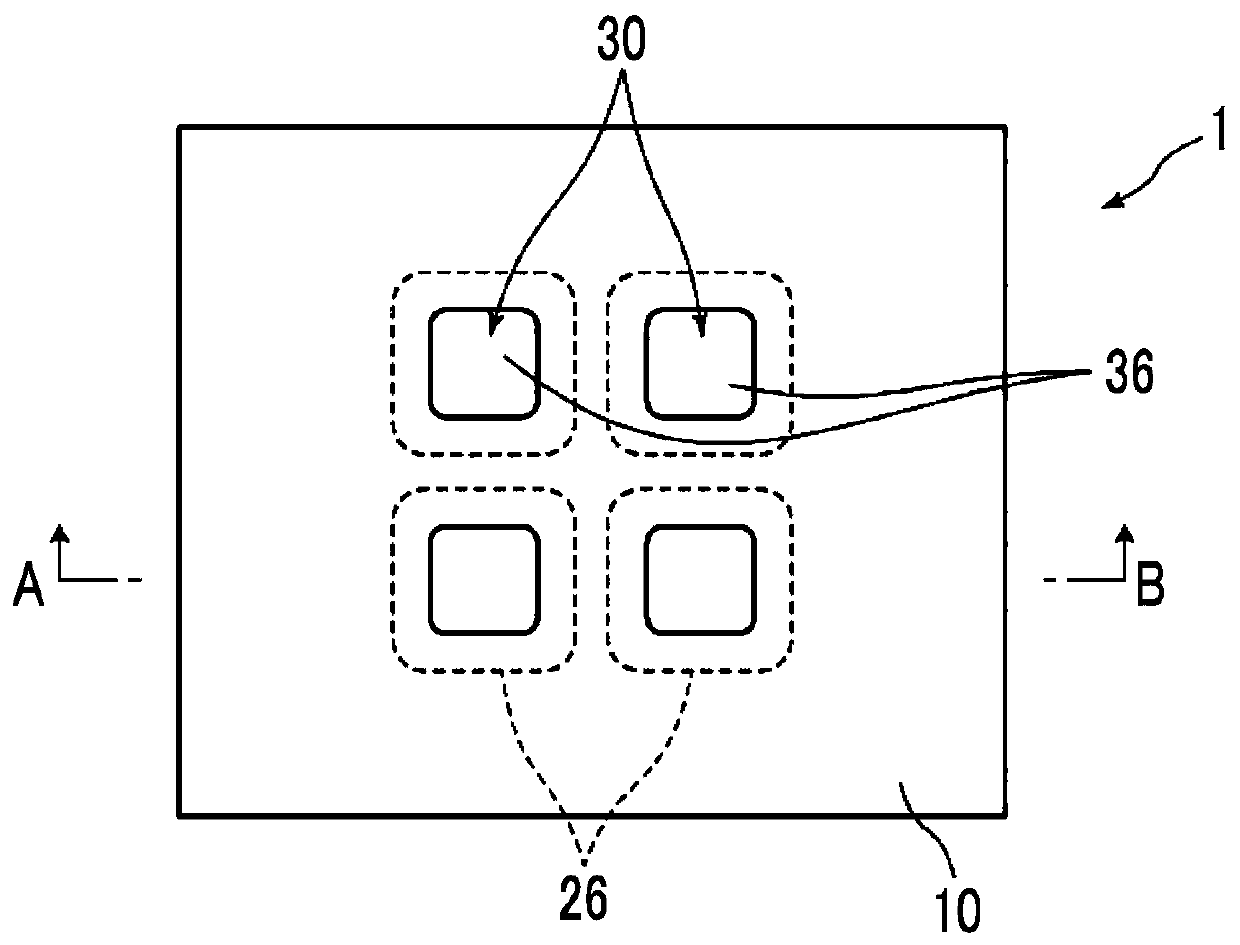
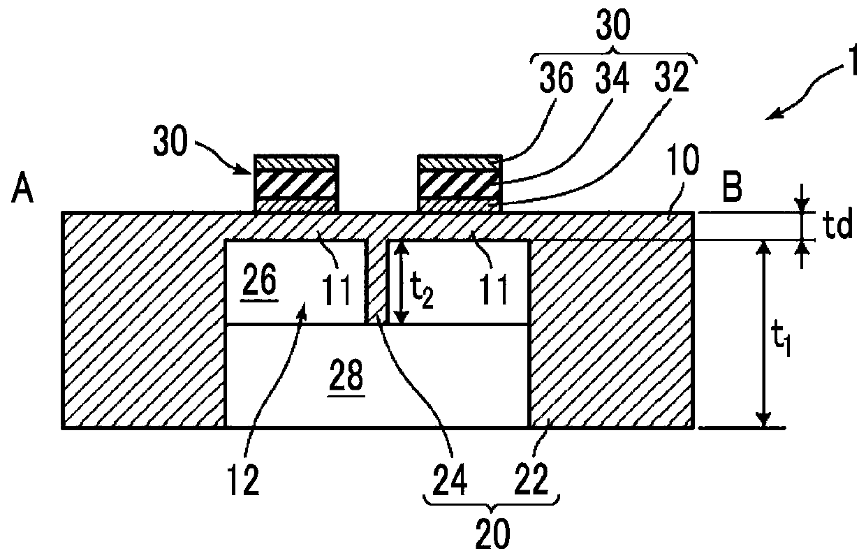
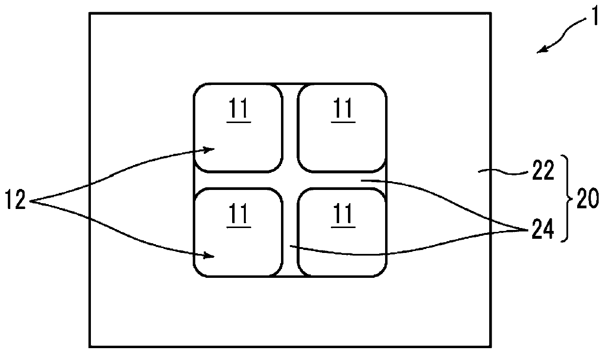
The present invention provides a piezoelectric microphone chip and a piezoelectric microphone, the piezoelectric microphone chip having high sensitivity to a sound pressure detection signal and beingsuitable for mounting to a package. The piezoelectric microphone is provided with: one thin plate; a diaphragm support structure that is provided on one surface of the thin plate, and comprises an outer edge support part for supporting the outer edge of the thin plate and a separating support part for dividing the thin plate into a plurality of diaphragms in cooperation with the outer edge supportpart; one or more piezoelectric conversion parts each formed by stacking, on each of the diaphragms, a first electrode, a piezoelectric film and a second electrode in order from the side of each of the diaphragms; and a signal detection circuit for detecting outputs from the piezoelectric conversion parts provided on the plurality of diaphragms, wherein the relationship among the thickness t1 ofthe outer edge support part, the thickness t2 of the separating support part, and the thickness td of the thin plate 10 is 13.3*td < t2 < t1-20 [mu]m.

Description

technical field [0001] The present invention relates to a piezoelectric microphone chip provided with a piezoelectric element as a sensor and a piezoelectric microphone provided with the chip, and particularly relates to a MEMS (Micro Electro Mechanical System) manufactured using semiconductor integrated circuit manufacturing technology. Systems: microelectromechanical systems) piezoelectric microphone chip and piezoelectric microphone. Background technique [0002] In recent years, a small microphone with a high S / N ratio has been demanded, and MEMS microphones have attracted attention as a solution to this. Among them, the MEMS piezoelectric microphone utilizing the piezoelectric effect is expected to be widely used in existing electrostatic piezoelectric microphones because it does not require a driving bias and has a wide dynamic range of displacement. [0003] As a conventional structure for sound pressure detection using a MEMS piezoelectric microphone, there is a dia...

Claims


Application Information

Patent Timeline
Patent Type & Authority Applications(China)
IPC IPC(8): H04R17/02B81B3/00H01L41/053H01L41/113H01L41/187H04R1/02H04R1/06H04R3/00
CPCB81B3/00H04R17/02H04R3/005H04R2201/003H04R7/18H04R7/06H04R2410/03H04R1/06H10N30/30H10N30/88
Inventor 直野崇幸
Owner FUJIFILM CORP
Why Eureka
Try Eureka