Eureka AIR delivers breakthrough ideas for toughest innovation challenges, trusted by R&D personnel around the world.

Cement component powder grinding equipment

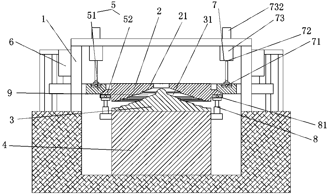
A grinding and cement technology, applied in cocoa, grain processing, food science, etc., can solve the problems of easy vibration of the mill, low power consumption, high cost of equipment procurement and maintenance, and achieve the effect of guaranteed grinding effect

Active Publication Date: 2019-12-24
福建福清万年青水泥有限公司
View PDF9 Cites 2 Cited by
  • Summary
  • Abstract
  • Description
  • Claims
  • Application Information

AI Technical Summary

Problems solved by technology

In addition, there is another grinding process, that is, pre-grinding plus tube milling. The process is relatively simple, and the power consumption is lower than the other two processes. Currently, vertical mills are used as pre-grinding more often, but sieves still need to be added. Grading process, and the mill is easy to vibrate when it is not well operated
[0003] Such as the cement pre-grinding equipment described in the authorized announcement number CN106269064B, which realizes the pre-grinding of cement through a vertical structure, and realizes the post-grinding process by setting a belt edge between the rolling plate and the load-bearing plate. The sending out of the components and the interference problem caused by the height of the rib structure with the material make the product can only grind the raw material to a level slightly smaller than its height, resulting in the need for subsequent fine grinding equipment to complete the final grinding requirements , the required equipment purchase and maintenance costs are high, and the process flow is long. Furthermore, because of the difficulty of replacing the belt material edge, it can only produce products with a small range of particle sizes, and the adaptability is poor.

Method used


Image

  • Cement component powder grinding equipment
  • Cement component powder grinding equipment
  • Cement component powder grinding equipment

Examples


Embodiment 2

[0038] The technical scheme described in embodiment two is similar to embodiment one, and its difference is:

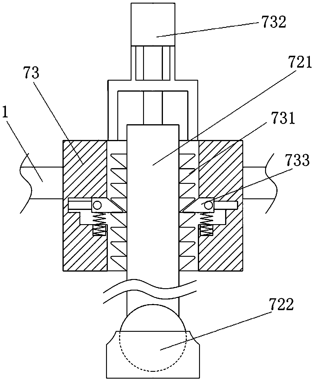
[0039] like Figure 5 As shown, the cylinder 721 is a cylinder 721, and the ratchet 731 is linearly distributed on one side of the cylinder 721 cylinder along the radial direction of the cylinder 721. The splines 723 connected to the adjustment frame 73 are evenly distributed on the circumference of the axis, so that compared with the first embodiment, it has better contact balance and better stability in all directions.


PUM


Abstract

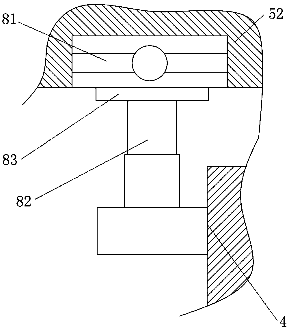
The invention aims to provide cement component powder grinding equipment, and aims to solve the problems existing in the prior art. The equipment comprises a rolling disc, a weight bearing disc, a weight bearing foundation and a rotary driver, wherein the rolling disc, the weight bearing disc, the weight bearing foundation and the rotary driver are sequentially arranged in a supporting frame in adownward stacked mode, and the rotary driver is connected with a gear pair and used for driving the grinding disc; the gear pair comprises a first gear ring and a second gear ring, wherein the first gear ring and the second gear ring mesh with each other in an oblique-teeth mode, the upper side of the first gear ring is connected with an adjusting device, and the lower side of the second gear ringis connected with a supporting device; and the lower surface of the grinding disc is provided with a rolling surface which is outwards stepped down in the radial direction, the upper surface of the weight bearing disc is provided with a weight bearing surface which is outwards stepped down in the radial direction, the rolling surface and the weight bearing surface are combined to form a powder grinding cavity, and the vertical height of the powder grinding cavity is gradually reduced from the center to the outside. According to the cement component powder grinding equipment, cement componentscan be fully ground in single equipment until the final required particle size is directly output, and meanwhile the particle size of produced objects is conveniently adjusted according to productionrequirements so that the equipment cost can be reduced, and economic benefits can be improved.

Description

technical field [0001] The invention relates to the technical field of cement production equipment, in particular to cement component grinding equipment. Background technique [0002] At present, in the process of cement grinding, roller press pipe mill and vertical mill final grinding are two mainstream grinding processes. The system of roller press and pipe mill is more complicated and there are many equipments; the final grinding process of vertical mill is simple, but the operation of vertical mill itself is complicated, and the mill is prone to vibration. In terms of power consumption, the two are basically the same. In addition, there is another grinding process, that is, pre-grinding plus tube milling. The process is relatively simple, and the power consumption is lower than the other two processes. Currently, vertical mills are used as pre-grinding more often, but sieves still need to be added. Grading process, and the mill is easy to vibrate when it is not well op...

Claims


Application Information

Patent Timeline
IPC IPC(8): B02C7/04B02C7/14B02C7/12
CPCB02C7/04B02C7/12B02C7/14
Inventor 蒋云义
Owner 福建福清万年青水泥有限公司
Why Eureka
Eureka Blog
Learn More