Waste paper treatment device of adhesive sticker machine

A treatment device and waste paper technology, which is applied in the direction of raw material pretreatment, etc., can solve the problems such as the single unusable waste paper ink scouring, affecting waste treatment, etc., to achieve the effect of facilitating classification and treatment, reducing waste treatment process, and optimizing environmental protection process

Inactive Publication Date: 2019-12-24
云和县宏峰模具厂
View PDF1 Cites 0 Cited by
  • Summary
  • Abstract
  • Description
  • Claims
  • Application Information

AI Technical Summary

Problems solved by technology

[0003] Chinese patent (authorized announcement number: CN208309267U) has announced a new type of waste paper processing device for self-adhesive machines. The water mist nozzle installed can wet the paper sheets with water and make them fall on the conveyor belt without falling everywhere. , can also wash away the ink on the waste paper; the ink on the waste paper of the self-adhesive machine is the main source of pollution, and it is also an important factor affecting the subsequent waste treatment. A single water mist nozzle cannot effectively remove the ink on the waste paper. Ink flushing will still affect subsequent waste disposal

Method used


Image

  • Waste paper treatment device of adhesive sticker machine
  • Waste paper treatment device of adhesive sticker machine
  • Waste paper treatment device of adhesive sticker machine

Examples


Embodiment 1

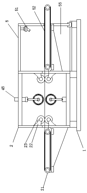
[0023] see figure 1 , a waste paper treatment device for a self-adhesive machine, comprising a frame 1, the frame 1 is provided with an ink removal chamber 2 and an ink flushing chamber 5, the feed port and the discharge port of the ink removal chamber 2 The positions are all equipped with a fixed frame 22, the fixed frame 22 is equipped with a guide roller 23, the feeding end of the ink removal chamber 2 is equipped with a primary conveyor belt 21, and the ink flushing chamber 5 is provided with a secondary The conveyor belt 52, and the top of the ink flushing chamber 5 is provided with a shower head 51. The ink removal chamber 2 is used to rub off the ink on the surface of the tape, and the ink flushing chamber 5 removes the ink by flushing.

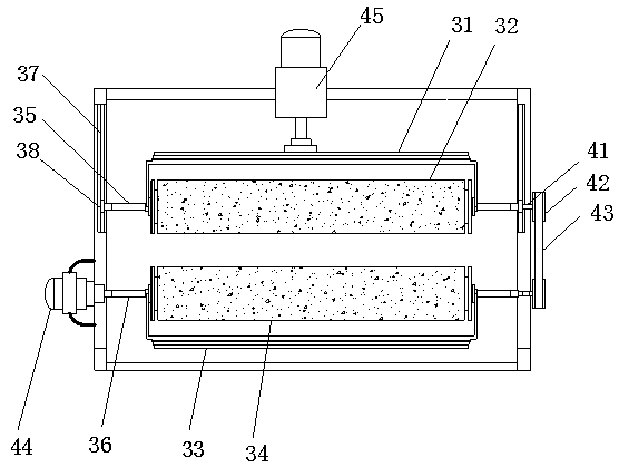
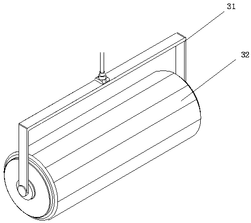
[0024] see figure 2 and image 3 , movable frame 31 and fixed frame 33 are respectively installed in described ink removal cavity 2, movable friction roller 32 is installed on described movable frame 31, fixed friction roller 34 is...

Embodiment 2

[0029] see Figure 4 , this embodiment serves as a further optimization of Embodiment 1, on the basis of which, partitions 53 are provided on both sides of the secondary conveyor belt 52, and several water permeable holes 54 are provided on the partitions 53. The bottom of the ink removal chamber 2 is provided with a water accumulation chamber 55 . During the flushing operation, the partition board 53 places the paper tape and is skewed after being impacted by the water flow. After flushing, the water flow carries the ink and flows into the water accumulation chamber 55 from the permeable hole 54 .


PUM


Abstract

The invention relates to non-setting adhesive process production. The waste paper treatment device of the non-setting adhesive machine comprises a machine body, including a machine frame, wherein an ink removing cavity and an ink washing cavity are formed in the rack; a movable frame and a fixed frame are respectively mounted in the printing ink removing cavity; a movable friction roller is mounted on the movable frame; a fixed friction roller is mounted on the fixed frame; the movable friction roller and the fixed friction roller are installed in an inner cavity of the ink removing cavity through a movable roller shaft and a fixed roller shaft correspondingly. Guide rails are further arranged on the left side wall and the right side wall of the ink removing cavity, guide blocks are installed at the two ends of the movable roller shaft and installed in the corresponding guide rails in an embedded mode, an electric push rod is installed at the top of the ink removing cavity, and the bottom end of the electric push rod extrudes downwards to make contact with the movable frame. Ink stains and paper tapes are effectively separated through clamping friction, subsequent classification treatment is facilitated, and the environmental protection process of an enterprise is optimized.

Description

technical field [0001] The invention relates to the production of self-adhesive technology, in particular to a waste paper processing device of a self-adhesive machine. Background technique [0002] Self-adhesive machines are commonly used equipment in the packaging industry. With the rapid development of society, various packaging products have been produced. In the labeling of self-adhesive machines, waste paper for self-adhesive bottom paper will be produced. The existing It is not easy to collect waste paper from self-adhesive machines, so many factories discard it directly or incinerate it directly, which wastes resources and pollutes the air. Some paper scraps are not completely collected, which may cause mechanical failure. For this reason, we propose a new type of waste paper processing device for self-adhesive machines. . [0003] Chinese patent (authorized announcement number: CN208309267U) has announced a new type of waste paper processing device for self-adhesi...

Claims


Application Information

Patent Timeline
Patent Type & Authority Applications(China)
IPC IPC(8): D21B1/02
CPCD21B1/02
Inventor 林迺建
Owner 云和县宏峰模具厂
Why Eureka
Try Eureka