A corner lens optical fiber array and its manufacturing method

A lens fiber and fiber array technology, applied in the field of optical fiber transmission, can solve the problems of difficult to meet high sensitivity and high bandwidth, achieve the effect of low premise investment and improve coupling efficiency

Active Publication Date: 2020-10-02
WUHAN POWERISE OPTOELECTRONICSAL TECH
View PDF16 Cites 0 Cited by
  • Summary
  • Abstract
  • Description
  • Claims
  • Application Information

AI Technical Summary

Problems solved by technology

However, the coupling efficiency of the fiber array can only reach 40% to 50% at the transmitting end, which is difficult to meet the requirements of high sensitivity and high bandwidth.

Method used


Image

  • A corner lens optical fiber array and its manufacturing method
  • A corner lens optical fiber array and its manufacturing method
  • A corner lens optical fiber array and its manufacturing method

Examples


Embodiment Construction

[0036] The principles and features of the present invention are described below in conjunction with the accompanying drawings, and the examples given are only used to explain the present invention, and are not intended to limit the scope of the present invention.

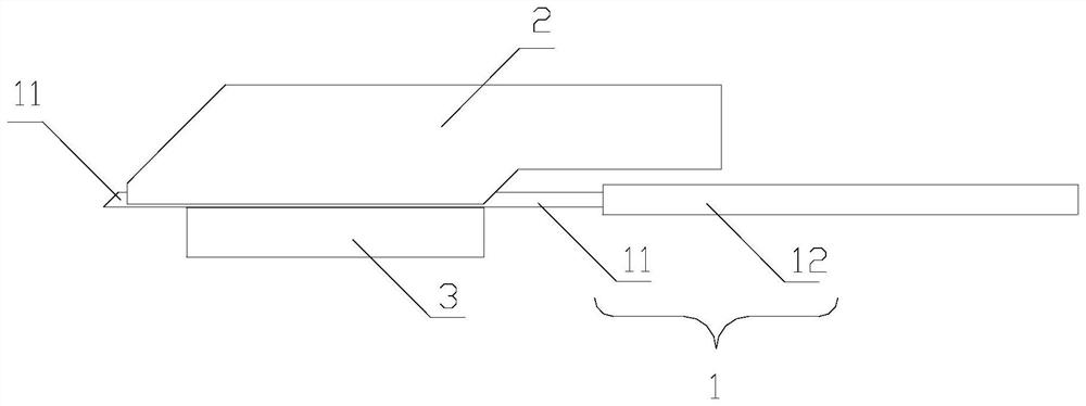
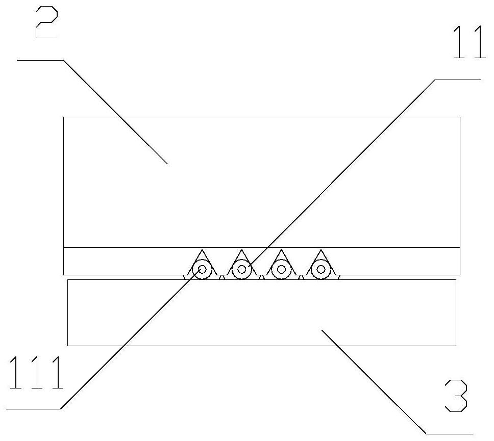
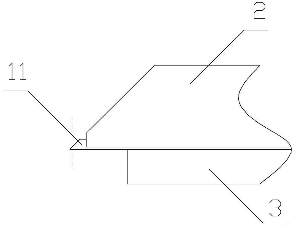
[0037] Such as figure 1 and figure 2 Shown, a kind of corner lens optical fiber array of the present invention, described optical fiber array comprises optical fiber microstrip 1, grooved substrate 2 and cover sheet 3, and described optical fiber microstrip 1 comprises the bare fiber end 11 that removes optical fiber layer and There is a microstrip end 12 with an optical fiber layer applied, the grooved substrate 2 is formed with a plurality of V-shaped grooves arranged in parallel arrays for placing the bare fiber end 11, and the bare fiber end 11 is formed from The front end of the V-shaped groove protrudes, and the cover sheet 3 presses the bare fiber end into the V-shaped groove, and the grooved substrate 2, c...


PUM

PropertyMeasurementUnit
angleaaaaaaaaaa
angleaaaaaaaaaa

Abstract

The invention relates to an angle lens optical fiber array and a fabrication method thereof. A bare fiber end surface of the optical fiber array is an inclined optical plane, the front end, located ina region outside a fiber core, on the optical plane cuts off a tip end in a vertical plane, a convex-surface lens protruding forwardly is formed at a cut-off section, and the focus of the convex-surface lens is located within the fiber core of the optical fiber. According to the angle lens optical fiber array and the fabrication method thereof, the optical path angle can be rapidly realized basedon the optical fiber array, 40%-50% of the coupling efficiency is achieved compared with the conventional optical fiber array, cutting processing of the end surface of the optical fiber array is performed and the convex-surface lens protruding forwardly is formed so that the end surface of the optical fiber array has a focusing function, the coupling efficiency is greatly improved, 60%-70% of thecoupling efficiency can be achieved, and most scene application requirements can be met; and advantages of short delivery cycle, low premise investment and wide temperature resistance can satisfy themodernized requirement of rapid iteration with higher and higher requirement.

Description

technical field [0001] The invention relates to the technical field of optical fiber transmission, in particular to a corner lens optical fiber array and a manufacturing method thereof. Background technique [0002] There are two mainstream 90° angle coupling schemes on the market: the lens coupling scheme of multi-stage condenser lens plus one-stage light path reflection, and the fiber array scheme of directly realizing the 90° rotation angle of the optical path by polishing the fiber at a 45° angle. The coupling efficiency of the lens coupling scheme can be as high as 80-90%, but the lens needs to be molded and injected, which takes a long time for mold processing, and the mold cost for the lens is also expensive. The characteristics of long time and high investment in the early stage of the lens coupling solution determine that this solution is only suitable for mature large-scale application cases, and is not suitable for the high responsiveness requirements of rapid ite...

Claims


Application Information

Patent Timeline
Patent Type & Authority Patents(China)
IPC IPC(8): G02B6/26G02B6/25
CPCG02B6/25G02B6/262
Inventor 李志远吴俊
Owner WUHAN POWERISE OPTOELECTRONICSAL TECH
Why Eureka
Try Eureka