Method and device for controlling intelligent edge pulling machine system

A control method and control device technology, applied in computer control, program control, signal transmission system, etc., can solve the problems of single use of operation station, interference, high cost, etc., reduce the amount of sent data, increase processing speed, and avoid setting wires cable effect

Active Publication Date: 2019-12-27
BENGBU TRIUMPH ENG TECH CO LTD
View PDF13 Cites 0 Cited by
  • Summary
  • Abstract
  • Description
  • Claims
  • Application Information

AI Technical Summary

Problems solved by technology

However, all the control signals on site are collected and sent to remote control cabinets through control cables, and are sent to field devices through information processing through the PLC in each control cabinet. The distance between them is relatively long, and a large number of signals are transmitted and collected through cables. Cause mutual interference, and use a large number of cable network lines, the cost is high
The information data is collected and summarized on the upper computer, and the

Method used


Image

  • Method and device for controlling intelligent edge pulling machine system
  • Method and device for controlling intelligent edge pulling machine system
  • Method and device for controlling intelligent edge pulling machine system

Examples


Embodiment 1

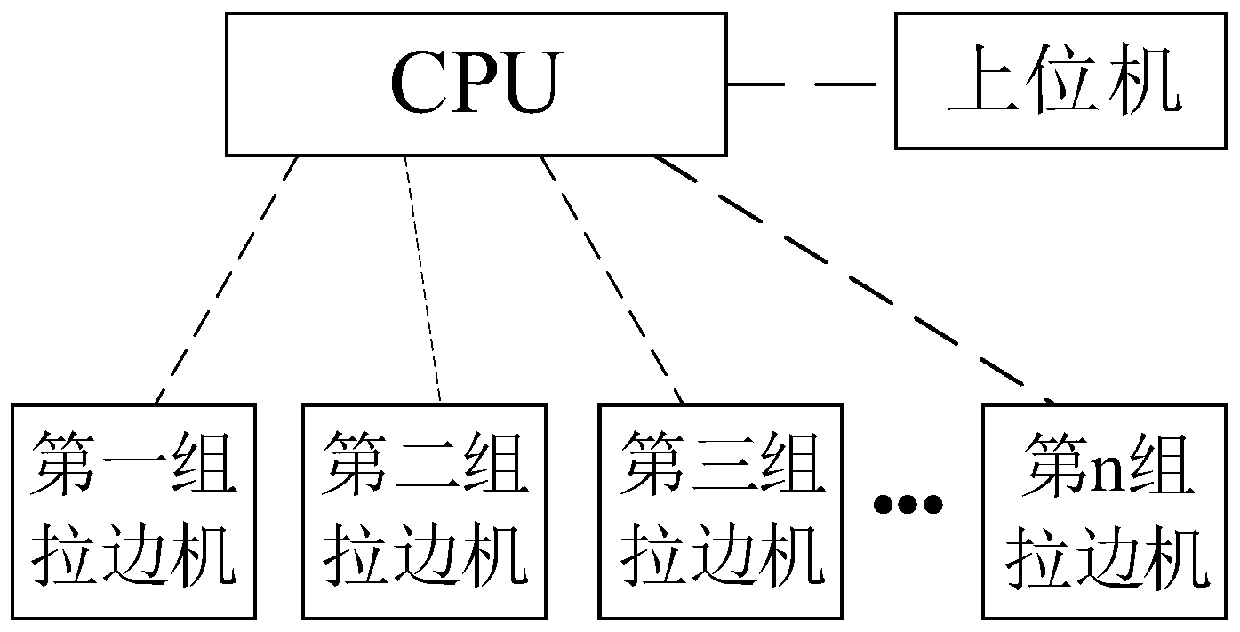
[0029] A control method for an intelligent edge-drawing machine system, the method comprising: the CPU in the main control cabinet receives data of several edge-drawing machines through wireless transmission and sends the data to the upper computer; figure 1 Shown is a schematic diagram of the connection between the CPU, the edge machine and the host computer.

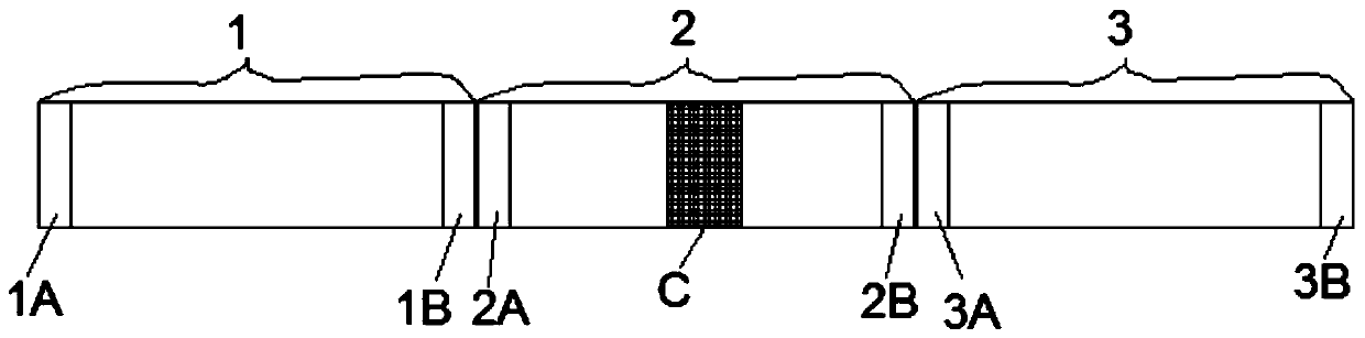
[0030] For each edge pulling machine, the edge pulling machine compares the data frame corresponding to the current cycle with the data frame corresponding to the previous cycle of the current cycle in the current cycle, and compares the data frame of the current cycle with the previous cycle The data item corresponding to the same position in the data frame of the period is replaced with a preset mark; and then the data frame of the current period after the preset mark is replaced is sent to the CPU. Such as figure 2 As shown, it is a schematic diagram of sending data to the CPU by the edge pulling machine. 1, 2, an...

Embodiment 2

[0040] Corresponding to Embodiment 1 of the present invention, Embodiment 2 of the present invention also provides an intelligent edge pulling machine system control device, which includes:

[0041] The data transceiver module is used for the CPU in the main control cabinet to receive the data of several edge pulling machines through wireless transmission and send the data to the host computer; the data transceiver module includes a comparison unit and a data processing unit;

[0042] The comparison unit is used to compare the data frame corresponding to the current cycle with the data frame corresponding to the previous cycle of the current cycle in the current cycle for each edge pulling machine;

[0043] The data processing unit is used to replace the data item in the data frame of the current cycle with the same data item in the corresponding position in the data frame of the previous cycle with a preset mark; and then send the data frame of the current cycle after replacin...


PUM


Abstract

The invention discloses a method and a device for controlling an intelligent edge pulling machine system. The method comprises the following steps: receiving data of a plurality of edge pulling machines in a wireless transmission mode and sending the data to an upper computer by a CPU in a main control cabinet; when the data is sent to the CPU by each edge pulling machine, in staggered sending periods, sending the data in a time-sharing mode in a data frame, in the current period, comparing the data of the current edge pulling machine with the data sent to the CPU in the previous period of thecurrent period, marking parts with the same data, only sending the corresponding marks when the data is sent, directly sending the corresponding data of the parts with different data, after the datais sent to the CPU, and calling the data of the previous period of the current period corresponding to the marks in the parts with the same data. The method has the advantages that communication cables do not need to be arranged, the cost is low, and faults can be quickly removed by changing the data transmission mode and the communication mode.

Description

technical field [0001] The present invention relates to the field of network base station construction, and more specifically relates to a control method and device for an intelligent edge-drawing machine system. Background technique [0002] The edge pulling machine is one of the main equipments of float glass production, it plays an important role in throttling, thinning, accumulating thickness and controlling the direction of the original plate. Its principle is to rely on the edge pulley at the front end of the edge puller to pull the glass ribbon with a certain viscosity floating on the liquid surface of the tin bath to move forward. Inclination angle, etc., to control the thickness of the glass ribbon and stabilize the width of the glass ribbon. The quality of the edge machine control directly affects the output and quality of its glass. At the present stage, each pair of edge machines independently controls field devices, and uses two methods of Ethernet communicatio...

Claims


Application Information

Patent Timeline
IPC IPC(8): G05B19/042G08C17/02
CPCG05B19/042G08C17/02Y02P90/02
Inventor 杨华龙邢宝山叶坤郑纤秀王亮许新林李学武薛达徐智松张斌王磊
Owner BENGBU TRIUMPH ENG TECH CO LTD
Why Eureka
Try Eureka