
Control system for virtual power plant

A technology for control systems and virtual power plants, applied in electrical components, circuit devices, AC network circuits, etc., can solve the problems of difficult and micro-source reactive power distribution according to droop coefficient, poor power quality, and the lack of global adjustment capability of the system.

Active Publication Date: 2019-12-27
SHENZHEN POWER SUPPLY BUREAU
View PDF7 Cites 5 Cited by
  • Summary
  • Abstract
  • Description
  • Claims
  • Application Information

AI Technical Summary

Problems solved by technology

[0003] At present, virtual power plants often introduce virtual impedance to weaken the influence of resistive components in the line, so that the micro-source adopts inductive droop control. At the same time, the micro-source adopts improved droop control to meet the needs of various operating modes of the virtual power plant. However, for multi-voltage There are still some problems in the virtual power plant of the source-type micro-source network, which only relies on the droop control of the micro-source itself. First, due to the unequal voltage drop on each line impedance of the virtual power plant and the uneven load distribution, the micro The reactive power output by the source cannot be distributed according to the droop coefficient. A small output voltage difference will cause a large power error, which can easily cause the overcurrent of the converter. Secondly, the droop control is a kind of differential control. When the system When the power fluctuates greatly, the voltage and frequency of the system will exceed the allowable operating range. Again, the output power of the energy storage device in the virtual power plant is limited by it, and its output needs to be adjusted according to the economic dispatch of the system. Droop control, the virtual power plant has problems such as difficulty in realizing the distribution of reactive power of each micro-source according to the droop coefficient, poor power quality, and the system does not have the ability to adjust globally

Method used


Image

  • Control system for virtual power plant

Examples


Embodiment Construction

[0026] In order to make the above objects, features and advantages of the present invention more comprehensible, specific implementations of the present invention will be described in detail below in conjunction with the accompanying drawings. In the following description, numerous specific details are set forth in order to provide a thorough understanding of the present invention. However, the present invention can be implemented in many other ways different from those described here, and those skilled in the art can make similar improvements without departing from the connotation of the present invention, so the present invention is not limited by the specific implementations disclosed below.

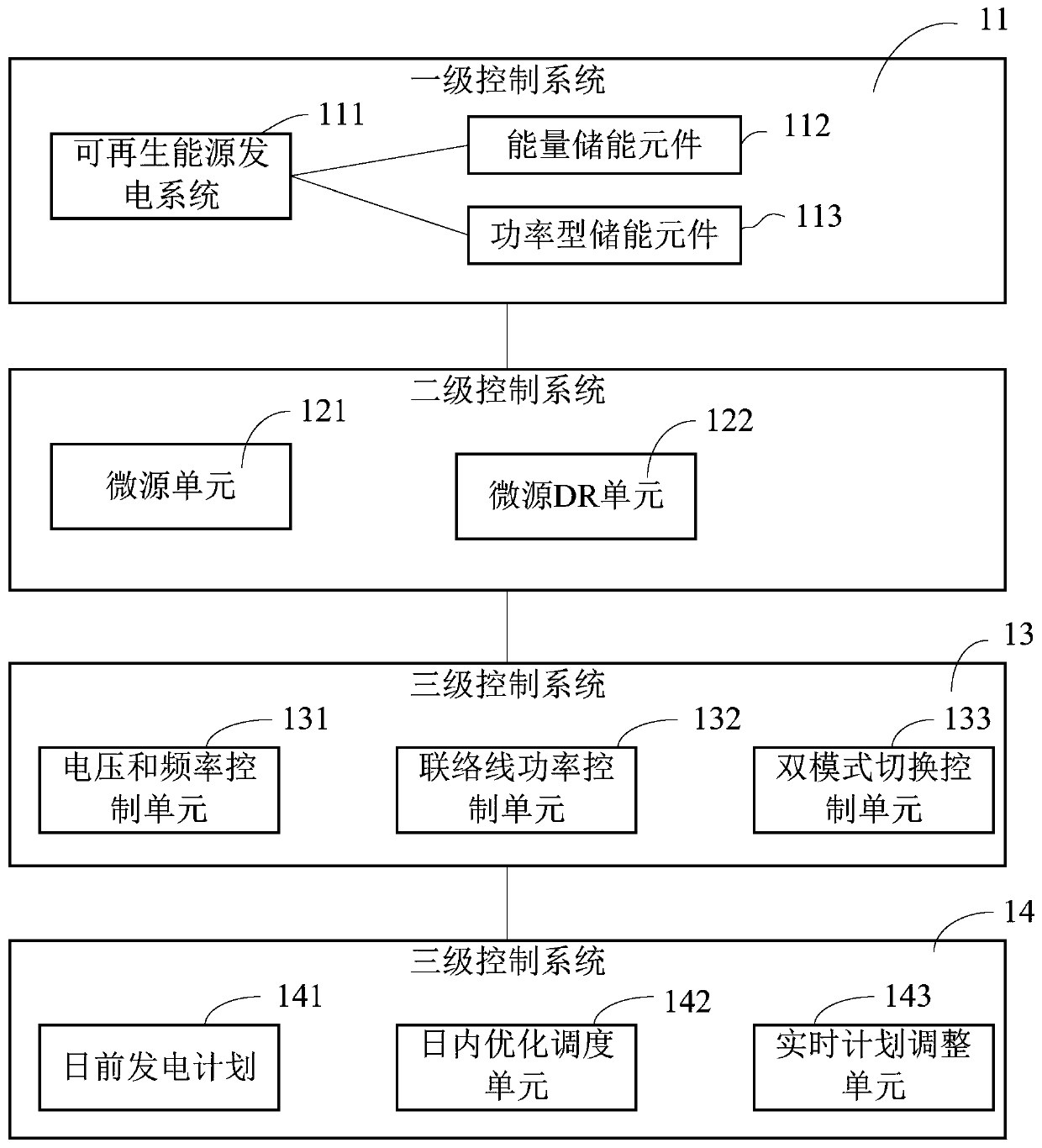
[0027] refer to figure 1 As shown in FIG. 1 , a schematic structural diagram of a virtual power plant control system provided by the present invention is shown. In this embodiment, the virtual power plant control system includes a hierarchical control system 1, which is characterized...


PUM


Abstract

The invention discloses a control system for a virtual power plant. The control system comprises a hierarchical control system; the hierarchical control system comprises a first-stage control system,a second-stage control system, a third-stage control system and a fourth-stage control system. According to the control system for the virtual power plant , on the basis of the operation characteristics of the virtual power plant, a virtual power plant hierarchical control strategy based on different time scales is provided; and therefore, the problem that it is difficult for the virtual power plant to realize droop coefficient-based reactive power distribution of each micro-source, the problem of poor electric energy quality and the problem that a system does not have a global regulation capability, and other problems can be solved through the hierarchical control system on different time scales and control levels; and the virtual power plant has a global coordination control capability while maintaining a certain local control capability.

Description

technical field [0001] The invention relates to the technical field of virtual power plants, in particular to a virtual power plant control system. Background technique [0002] At present, these distributed energy sources such as household power plants pose a serious threat to the security and reliability of the entire power grid. It is precisely because of the existence of these two contradictions that the current power system not only has energy waste, but also faces security problems. , the virtual power plant is born from this. The virtual power plant can efficiently and economically adjust the load of each peak-shaving unit, various energy storage equipment, and various electrical equipment, so as to achieve the purpose of increasing or decreasing load more economically on demand. For wind energy Virtual power plants also have a solution to the contradictions between distributed energy sources such as energy, solar energy, and the grid. Virtual power plants aggregate v...

Claims


Application Information

Patent Timeline
IPC IPC(8): H02J3/00H02J3/46
CPCH02J3/00H02J3/46
Inventor 焦丰顺邓永生李铎李志铿
Owner SHENZHEN POWER SUPPLY BUREAU
Learn More