A high-temperature acid flue gas deacidification device installed in a garbage incinerator

A technology of waste incinerator and incinerator, which is applied in gas treatment, separation method, dispersed particle separation, etc., can solve the problems of coking of heat exchange pipes, erosion and wear of heat exchange pipes, etc.

Active Publication Date: 2020-09-22
SOUTH CHINA UNIV OF TECH
View PDF6 Cites 0 Cited by
  • Summary
  • Abstract
  • Description
  • Claims
  • Application Information

AI Technical Summary

Problems solved by technology

[0005] If a commonly used deacidification device outside the incinerator is used for deacidification treatment, such as using a hydrated lime injector to directly spray lime slurry or dry hydrated lime powder into the three channels, some lime slurry or dry hydrated lime powder will adhere to the heat exchange pipes And under the action of high-temperature and high-velocity acidic flue gas, it quickly becomes hard dust particles, causing serious coking in the heat exchange pipes; some lime slurry or dry slaked lime powder turns into hard dust particles, with high temperature and high The high-speed acid flue gas flow caused severe scouring wear on the heat exchange tubes

Method used


Image

  • A high-temperature acid flue gas deacidification device installed in a garbage incinerator
  • A high-temperature acid flue gas deacidification device installed in a garbage incinerator
  • A high-temperature acid flue gas deacidification device installed in a garbage incinerator

Examples


Embodiment Construction

[0045] The present invention will be described in further detail below.

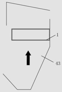
[0046] see Figure 14 , is a schematic diagram of the route of high-temperature acid flue gas flowing from the furnace 44 through the horizontal flue 45 . The high-temperature acid flue gas flows from the furnace 44 through the first channel 41, the second channel 42, the third channel 43, and the horizontal flue 45, and then flows to the reaction tower. There are several heat exchange pipes 451 in the horizontal flue 45 .

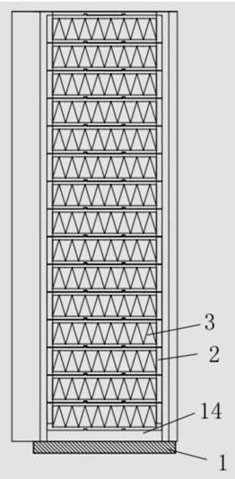
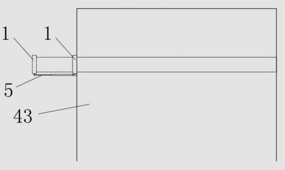
[0047] Such as Figure 1 ~ Figure 3 As shown, a high-temperature acid flue gas deacidification device installed in a garbage incinerator includes a base 1, which is slidably arranged on the upper part of the three-channel 43 in the incinerator, and can slide out from the upper part of the three-channel 43 to the outside of the incinerator Or slide into the upper part of the three channels 43 from the outside of the incinerator, the middle part of the base 1 is provided with a firs...


PUM


Abstract

The invention relates to a high-temperature acidic flue gas deacidification device arranged in a garbage incinerator. The high-temperature acidic flue gas deacidification device comprises: a base, which is slidably arranged at the upper part of a third channel in the incinerator, wherein a first through hole is formed in the middle part of the base and is arranged corresponding to the flowing direction of high-temperature acidic flue gas; and a plurality of carriers, which are detachably mounted on the base in sequence, wherein the surface of each carrier is fixedly connected with an adsorbent, and a gap allowing the high-temperature acidic flue gas to pass through is reserved between every two adjacent carriers. When the high-temperature acidic flue gas flows through the first through hole in the base and passes through the gaps among the carriers, the adsorbent can react with the high-temperature acidic flue gas, so corrosion of the high-temperature acidic flue gas to a heat exchanger on a horizontal flue is greatly reduced. Due to the fact that the adsorbent is fixedly connected to the carriers, the adsorbent cannot be separated from the carriers and attached to the heat exchanger, so the phenomenon of serious coking on a heat exchange pipeline cannot be caused, and serious erosive wear to the heat exchange pipeline after the adsorbent becomes hard particles is avoided.

Description

technical field [0001] The invention relates to the field of environmental protection equipment, in particular to a high-temperature acid flue gas deacidification device arranged in a garbage incinerator. Background technique [0002] With the rapid development of cities, the problem of garbage has become more and more serious. One of the garbage disposal methods that is being vigorously developed in our country is centralized incineration. [0003] The fuel for waste incineration is various types of waste with complex composition and extremely unstable calorific value. The flue gas generated during the waste incineration process contains a large number of harmful substances. Among these hazards, acidic flue gas such as hydrogen chloride, nitrogen oxides, and sulfur oxides account for a large proportion of waste incineration flue gas. After the high-temperature acid flue gas comes out of the furnace and passes through the three channels, it comes into contact with the hori...

Claims


Application Information

Patent Timeline
Patent Type & Authority Patents(China)
IPC IPC(8): B01D53/50B01D53/68B01D53/80
CPCB01D53/504B01D53/68B01D53/80B01D2251/404B01D2251/602B01D2251/604B01D2257/2045B01D2258/0291
Inventor 余昭胜杜斌云马晓茜
Owner SOUTH CHINA UNIV OF TECH
Why Eureka
Try Eureka