Quick-disassembly flexible large-diameter annular seam welding tool

A tooling and ring welding technology, applied in welding equipment, welding equipment, auxiliary welding equipment, etc., can solve problems such as poor stability, low assembly efficiency, and difficult movement, and achieve good stability, stable overall structure, and high repeatable assembly accuracy Effect

Active Publication Date: 2019-12-31
BEIJING SATELLITE MFG FACTORY
View PDF7 Cites 3 Cited by
  • Summary
  • Abstract
  • Description
  • Claims
  • Application Information

AI Technical Summary

Problems solved by technology

[0005] The technical problem solved by the present invention is: to overcome the deficiencies of the prior art, to provide a flexible large-diameter circular seam welding tool that can be quickly disassembled, and to solve the problems of the traditional column section circular seam welding tool such as difficulty in movement, poor stability, and low assembly efficiency

Method used


Image

  • Quick-disassembly flexible large-diameter annular seam welding tool
  • Quick-disassembly flexible large-diameter annular seam welding tool
  • Quick-disassembly flexible large-diameter annular seam welding tool

Examples


Embodiment Construction

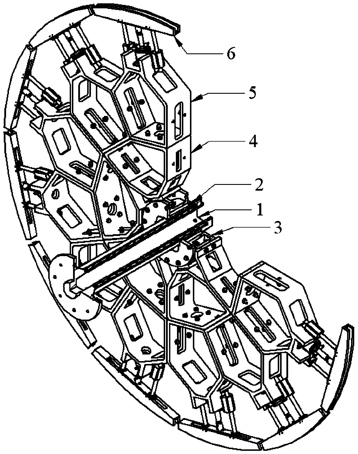
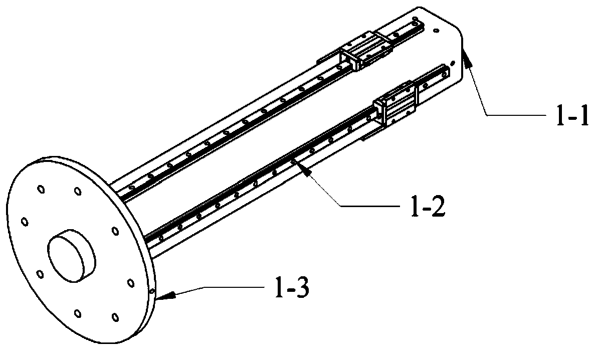
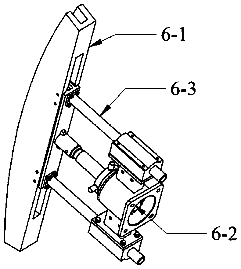
[0028] The present invention is a guide rail type large-scale cabin column girth welding tooling, which includes a square shaft 1, a fixed flange 2, a shaft sleeve flange 3, an inner frame 4, an outer frame 5 and an outer supporting arc block assembly 6; Detachable circumferential uniform structure, from the inside to the outside are square shafts, including square shaft 1, fixed flange 2, bushing flange 3, inner frame 4, outer frame 5 and outer support arc block assembly 6; the square shaft 1 is located The center position of the entire tooling; either end of the square shaft 1 is welded with a connecting flange to achieve assembly and fixation with the positioner of the welding system. There are four parallel linear guides on all sides to smoothly move the entire tooling along the axis; fixed Four sliding blocks are arranged on the inner side of flange 2 to realize the connection with the linear guide on the square shaft 1 and move smoothly along the axial direction; the inner...


PUM


Abstract

The invention discloses a guide rail type large cabin body column section annular welding tool. The welding tool comprises a square shaft, a fixed flange, a shaft sleeve flange, an inner frame, an outer frame and an outer supporting arc block assemblies; the whole tool is of a detachable circumferential uniform distribution structure, the tool comprises the square shaft from inside to outside andcomprises the square shaft, the fixed flange, the shaft sleeve flange, the inner frame, the outer frame and the outer support arc block assembly; the square shaft is located at the center position ofthe whole tool; a connecting flange is welded at any end of the square shaft, assembling and fixing between the position changing machine of the welding system and the square shaft are achieved, fourparallel linear guide rails are arranged on the four sides of the square shaft, and the four parallel linear guide rails are used for smoothly moving the whole tool in the axial direction; Four sliding blocks are arranged on the inner side of the fixed flange to be connected with a linear guide rail on the square shaft and smoothly move along the axial direction; the inner frame, the outer frame and the shaft sleeve flange are sequentially connected with each other through hinge hole bolts to provide a radiation type extension and a repeatable disassembly function; and the outer supporting arcblock assemblies are uniformly arranged on the outermost circumference of the tool and are connected with the outer frame, and mechanical lead screws are arranged on the outer supporting arc block assemblies, so that the telescopic of the arc blocks are achieved, and the top tightening assembly of the column section annular weld joint is met.

Description

Technical field [0001] The invention relates to a flexible large-diameter circumferential seam welding tool that can be quickly disassembled and belongs to the technical field of spacecraft welding technology. Background technique [0002] At present, the maximum diameter of the circular seam of the aluminum alloy cabin column section of the large spacecraft is 4 meters, and the wall thickness is more than 5mm. The circular seam of the column section is welded by the variable polarity plasma arc welding process. Due to the structural limitation of closed circumferential seams, traditional fixed integral casting welding tooling cannot meet the requirements of assembly and welding of such closed circumferential seams. Movable internal support tooling must be used to form welding pre-tightening in the radial butt of the weld. force. [0003] When the diameter of the circumferential seam of the cabin body reaches 4 meters, in order to ensure good overall rigidity of the welding toolin...

Claims


Application Information

Patent Timeline
IPC IPC(8): B23K10/02B23K37/04
CPCB23K10/02B23K37/0435
Inventor 曾如川葛一凡魏松张斌杜会桥姜坤郑雪松龙海东王宁
Owner BEIJING SATELLITE MFG FACTORY
Why Eureka
Try Eureka