2D (two-dimensional) laser positioning method of door and window on train body of train

A laser positioning and car body technology, applied in the field of physics, can solve the problems of low accuracy of train window assembly and end wall drilling

Active Publication Date: 2019-12-31
SHANGHAI RO INTELLIGENT SYST
View PDF8 Cites 2 Cited by
  • Summary
  • Abstract
  • Description
  • Claims
  • Application Information

AI Technical Summary

Problems solved by technology

[0003] The purpose of the present invention is to provide a 2D laser positioning method for train body doors and windows. The 2D laser positioning method for tr

Method used


Image

  • 2D (two-dimensional) laser positioning method of door and window on train body of train
  • 2D (two-dimensional) laser positioning method of door and window on train body of train
  • 2D (two-dimensional) laser positioning method of door and window on train body of train

Examples


Embodiment 1

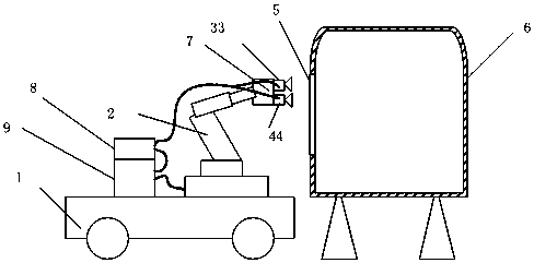
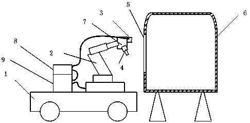
[0078] Such as figure 2 As shown, the equipment used in the 2D laser positioning method for doors and windows of a train body in the present invention includes an AGV trolley (automatic guided transport vehicle) 1 and a manipulator 2, and the manipulator 2 is arranged on the automatic guided transport vehicle 1 Above, the end of the manipulator 2 is also provided with a clamp 7, the clamp 7 is fixedly provided with a 2D laser sensor 3, and the clamp 7 is also provided with an operating tool 4, and the 2D laser sensor 3 is connected with a computer 8, and the manipulator 2 is connected with a controller 9, and the controller 9 is connected with the computer 8.

[0079] Further, the automatic guided transport vehicle 1 is manually driven to one of the window frames 5 of the car body 6, and the tool 7 on the manipulator 2 is controlled by a teaching method to install or process the window frame 5, Save the installation and processing track, use the teaching method to control th...

Embodiment 2

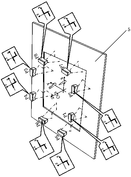
[0082] Such as Figure 5 As shown, the present invention provides a 2D laser positioning method for train body doors and windows, comprising the following steps:

[0083] 1) A process of calibrating the window frame of the train body door and window using the device of embodiment 1, the described process of calibrating the window frame of the train body door and window is: manually controlling the automatic guided transport vehicle to arrive at a pair of train The position where the window frame of the car body door and window is roughly positioned; the center of the door window frame of the train car body is set as the manipulator base coordinate origin (the method of the present invention is insensitive to the selection of the center point, allowing an error within 10mm), as shown Teach the manipulator, use the operating tool on the end of the manipulator to install or process the window frame 5 of the car body, and save the installation and processing track;

[0084] 2) Ke...


PUM


Abstract

A 2D (two-dimensional) laser positioning method of a door and a window on a train body of a train includes a process of performing calibration measurement on the train body of the train, wherein the process includes the steps of: first, manually moving an AGV (automatic guided vehicle) to a working station, positioning the AGV through visual observation, and setting the center position of a door and window frame as the manipulator base coordinate origin; indicating a manipulator to operate, and saving a trajectory of the manipulator as a work trajectory; indicating the manipulator to perform the calibration measurement; performing the calibration measurement on trisection positions of each edge of the frame, indicating the manipulator to carry a 2D sensor for scanning the 2D outline of theframe and record data, then calculating out six freedom degree coordinate value of the frame, and using the coordinate value as calibration position value; keeping a calibration measurement path of the manipulator as a path of following measurement work; and then moving the AGV to all stations to perform operation, calculating coordinate deviation between the current frame coordinate and the calibration position value, invoking the work trajectory of the manipulator, compensating the coordinate deviation, and obtaining a new work trajectory. The 2D laser positioning method of the door and thewindow on the train body of the train improves robustness and usability of a system, and is easy in calibration.

Description

Technical field: [0001] The invention relates to the field of physics, in particular to measurement technology, in particular to a 2D laser positioning method for doors and windows of a train body. Background technique: [0002] At present, the window assembly of the train body and the drilling of the end wall are all manual operations, and the labor intensity is high. In order to improve production efficiency, automation transformation is required. Due to the large size of the car body, it is unrealistic to move the car body to the production line. Therefore, the preferred automation solution is to fix the car body on the tooling. Various automatic equipment are designed as It is mobile and performs various automatic operations around the car body. For mobile devices, the most basic requirement is to be able to accurately locate the spatial position of the work surface. In the prior art, such as figure 1 As shown, using AGV trolley 1 positioning, 3D camera 33 visual posi...

Claims


Application Information

Patent Timeline
IPC IPC(8): B25J9/16
CPCB25J9/1664B25J9/1602
Inventor 覃江华高小嵩
Owner SHANGHAI RO INTELLIGENT SYST
Why Eureka
Try Eureka