Automatic quenching device for gear machining

A quenching device and automatic technology, applied in the field of gear processing, can solve the problems of hand burns of staff, heavy workload of workers, low production efficiency, etc., and achieve the effects of low manufacturing cost, convenient control and high production efficiency

Active Publication Date: 2019-12-31
泰州市新亚传动设备有限公司
View PDF11 Cites 6 Cited by
  • Summary
  • Abstract
  • Description
  • Claims
  • Application Information

AI Technical Summary

Problems solved by technology

[0005] The purpose of the present invention is to provide an automatic quenching device for gear processing, to solve the above-mentioned background technology. The existing high-frequency quenching is generally to place the parts in the induction coil for heating and then put them into the cooling liquid for rapid cooling. In order to change the ferrite structure, during the high-frequency quenching operation, workers need to manually place a single gear in the induction coil intermittently. After heating, the worker uses clips or other components to take the gear out of the quenching equipment and put it into the cooling liquid for cooling. , In this process, the operation speed is slow, the production efficiency is low, the labor load of the workers is heavy, and the temperature of the quenching equipment is high when the quenching equipment is working, and it is easy to burn the hands of the workers.

Method used


Image

  • Automatic quenching device for gear machining
  • Automatic quenching device for gear machining
  • Automatic quenching device for gear machining

Examples


Embodiment Construction

[0026] The following will clearly and completely describe the technical solutions in the embodiments of the present invention with reference to the accompanying drawings in the embodiments of the present invention. Obviously, the described embodiments are only some, not all, embodiments of the present invention.

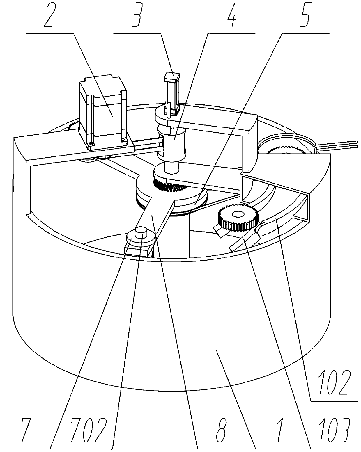
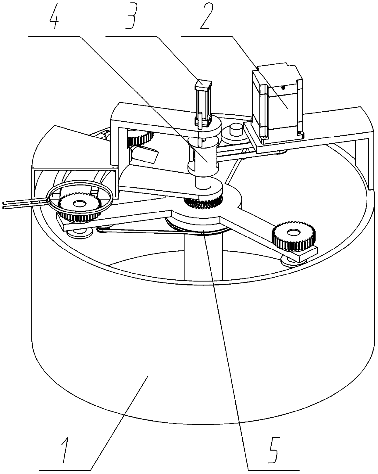
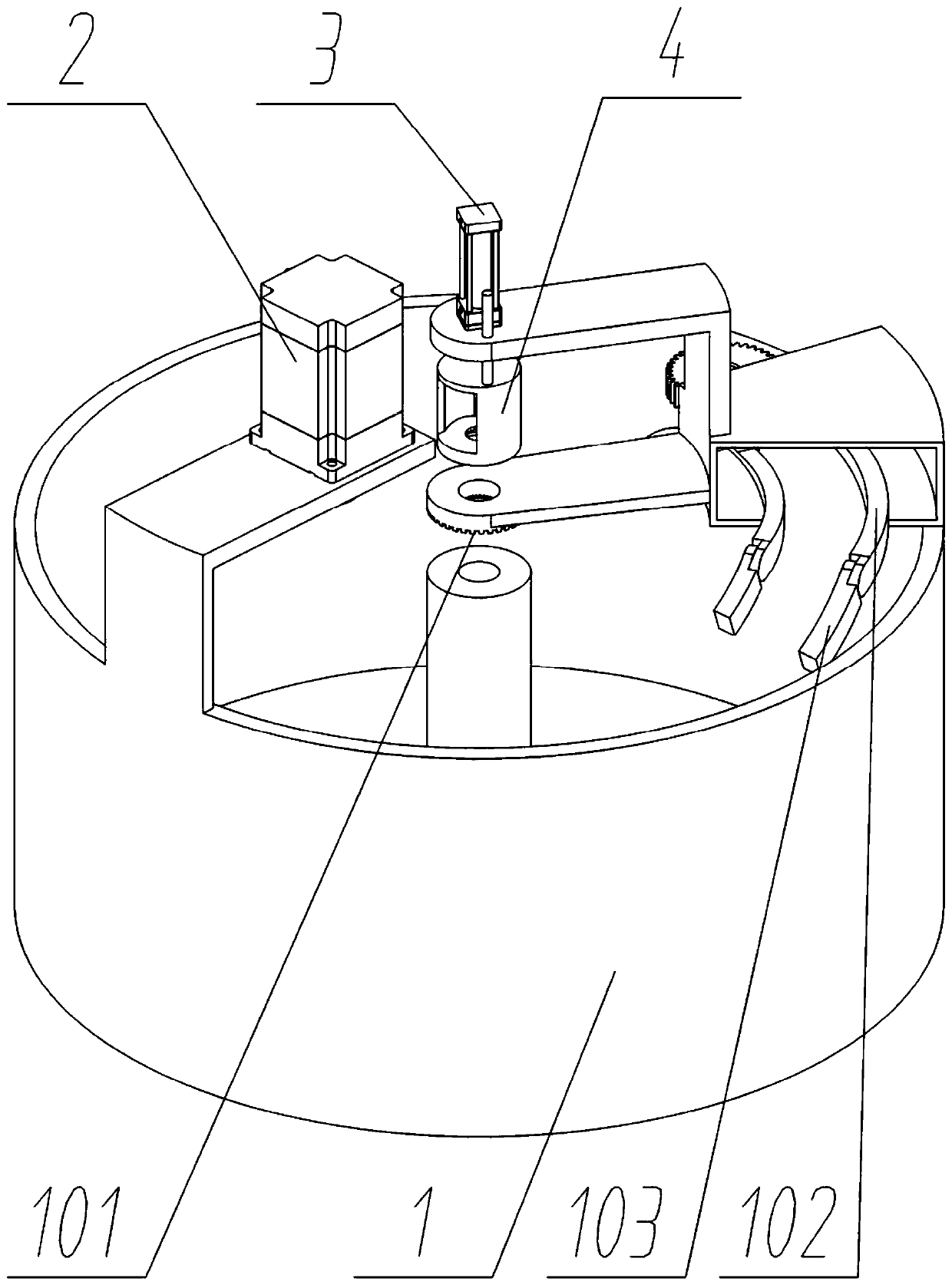
[0027] see Figure 1 to Figure 7 , an embodiment provided by the present invention: an automatic quenching device for gear processing, including a fuselage 1; a group of motors 2 fixedly connected to the left side of the upper end surface of the fuselage 1; a group of motors 2 fixedly connected to the central axis of the fuselage 1 The rotating central shaft 5; the rotating central shaft 5 also includes a driven pulley 501, a bottom end face tooth 502, and a speed change pulley 503. The upper end face of the rotating central shaft 5 is arranged in a circular array and fixedly connected with multiple groups of bottom end face teeth 502, The lower end surface of the be...


PUM


Abstract

The invention discloses an automatic quenching device for gear machining, and relates to the technical field of gear machining. The problems that in the existing high-frequency quenching process, theoperation speed is low, production efficiency is low, workloads on workers are high and the hands of the workers are easily scalded by a quenching device at a high working temperature are solved. Theautomatic quenching device comprises a machine body. A group of motors are fixedly connected with the upper end face of the machine body. A group of rotating middle shafts are axially connected with the center of the machine body. Three groups of part carriers are arrayed on and axially connected with the outside circumference of a carrying plate. A group of lifting blocks are fixedly connected with a piston rod of a cylinder. The carrying plate is axially connected with the lifting blocks. A group of middle belt wheels are axially connected with the upper portion of the right side of the machine body. The automatic quenching device is simple in structure, low in manufacturing cost, convenient to control, easy to operate, high in quenching speed and high in production efficiency and meanwhile prevents workers from touching heated gears to get scalded.

Description

technical field [0001] The invention relates to the technical field of gear processing, in particular to an automatic quenching device for gear processing. Background technique [0002] At present, most gears are made of carbon structural steel. In the process of gear manufacturing, quenching treatment is required to greatly improve the rigidity, hardness, wear resistance, fatigue strength and toughness of the steel, so as to meet the requirements of the gear. According to the requirements of use, high-frequency quenching is often used in the quenching process of gears. [0003] For example, application number: CN201410424144.X The present invention discloses a ring gear high-frequency quenching process, which belongs to the field of heat treatment technology, and includes the following steps: a. Adjust the cross-sectional shape of the quenching induction coil so that the cross-sectional shape of the quenching induction coil is a right-angled trapezoid , the quenching induc...

Claims


Application Information

Patent Timeline
Patent Type & Authority Applications(China)
IPC IPC(8): C21D9/32C21D1/10C21D1/63
CPCC21D1/10C21D1/63C21D9/0018C21D9/32Y02P10/25
Inventor 罗永军
Owner 泰州市新亚传动设备有限公司
Why Eureka
Try Eureka