
Spring chuck assembly of spinning winder

A spring collet and winding machine technology, which is applied to the clustering of newly extruded filaments, textiles and papermaking, etc., can solve the problems that affect the safety and efficiency of work, the fixing of the rotating shaft is not convenient, and the cushioning performance is not good, etc., to achieve Wide range of use, material saving, good stability and safety performance

Inactive Publication Date: 2019-12-31
SUQIAN RONGJIN INFORMATION TECH
View PDF0 Cites 0 Cited by
  • Summary
  • Abstract
  • Description
  • Claims
  • Application Information

AI Technical Summary

Problems solved by technology

[0004] The purpose of the present invention is to solve the problem that the spring collet of the spinning winding machine in the prior art has low stability when fixing the rotating shaft, and it is easy to shake during work, which affects the safety and efficiency of work, and the cushioning performance during work is not good. , the vibration is large, and the problem of inconvenient fixing of the rotating shaft is not enough, and a spring collet assembly of a spinning winding machine is proposed

Method used


Image

  • Spring chuck assembly of spinning winder
  • Spring chuck assembly of spinning winder
  • Spring chuck assembly of spinning winder

Examples


Embodiment 1

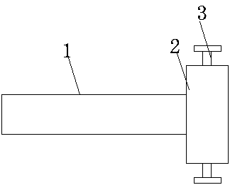
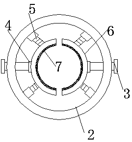
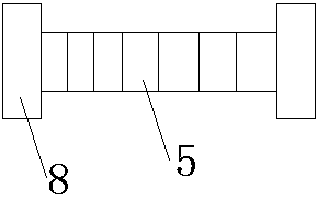
[0021] see Figure 1-5 As shown, a collet assembly of a spinning winding machine includes a main shaft 1 and a collet 2. Both sides of the collet 2 are connected with an inner ring 6, and one side of the inner ring 6 is connected to the collet 2. Several extrusion springs 5 ​​are installed between them, both ends of the extrusion spring 5 are respectively connected to the inner ring 6 and the collet 2 through the bolt head 8, and the middle side of the inner ring 6 is connected to the collet 2 through the fastening bolt 3, and the working After the two ends of the intermediate shaft are installed inside the collet 2, it is more stable, and the installation and disassembly are convenient. The rotating shaft is inside the collet 2, screw the fastening bolt 3, the squeeze spring 5 pushes the inner ring 6 into close contact with the outside of the rotating shaft, at the same time, the fastening bolt 3 can push the inner ring 6 to move, and the two inner rings 6 from both sides Th...

Embodiment 2

[0023] Additionally, according to Figure 1-5 As shown, the difference between it and the above-mentioned embodiment is that a bearing 4 is installed at the joint between the fastening bolt 3 and the inner ring 6, and one end of the fastening bolt 3 penetrates the collet 2, and when the fastening bolt 3 is screwed, the fastening One end of the bolt 3 rotates inside the inner ring 6 through the bearing 4, the inner ring 6 will not rotate with the fastening bolt 3, but can move under the promotion of the fastening bolt 3. The inside of the inner ring 6 and the collet 2 are provided with several screw holes 9, and the bolt heads 8 are respectively connected to the inner ring 6 and the collet 2 through the screw holes 9. The compression spring 5 is more convenient to install and disassemble in use. The inside of the rubber pad 7 is uniformly provided with several anti-slip platforms 10, which can increase the friction between the rubber pad 7 and the rotating shaft, so that the r...


PUM


Abstract

The invention discloses a spring chuck assembly of a spinning winder. The spring chuck assembly of the spinning winder comprises a main shaft, a spring chuck, a fastening bolt, a bearing, an extrusionspring, inner rings, a rubber pad, a bolt head, a screw hole, an antiskid table and a buffer layer. The spring chuck assembly of the spinning winder has the beneficial effects that two ends of a rotating shaft are stable after being mounted in the spring chuck, are not easy to shake, and are convenient to mount and dismount. The rotating shaft is arranged inside the spring chuck, the fastening bolt is screwed, the inner rings are pushed to be in close contact with the outside of the rotating shaft by the extrusion spring, meanwhile, the inner rings can be pushed to move by the fastening bolt,the two inner rings fix the rotating shaft from two sides, and the rotating shaft cannot fall off easily. The extrusion spring can be freely assembled and disassembled between the inner rings and thespring chuck through the bolt head. After being damaged, the extrusion spring can be freely replaced, materials are saved, the later maintenance cost is reduced, meanwhile, extrusion springs with different elastic coefficients can be mounted according to actual requirements, the requirements of different rotating shafts are met, and the application range is wide.

Description

technical field [0001] The invention relates to a spring chuck assembly, in particular to a spring chuck assembly of a spinning winding machine, which belongs to the application field of spinning winding machines. Background technique [0002] Winding machines include: lithium battery winding machine, capacitor winding machine, textile winding machine. According to the operation mode of the machine, it can be divided into: manual winding machine, semi-automatic winding machine and fully automatic winding machine. A main unit unit in the combined chemical fiber spinning unit; it refers to the process of further supplementary processing of the raw fibers (including filaments or short fiber bundles, etc.) obtained during melt spinning, and to make It is a special machine that forms a certain package form. Generally, the inside of the spinning winder includes a collet assembly for installing the rotating shaft. [0003] But the collet assembly of existing silk winding machine...

Claims


Application Information

Patent Timeline
Patent Type & Authority Applications(China)
IPC IPC(8): D01D7/00
CPCD01D7/00
Inventor 王娇付丽丽
Owner SUQIAN RONGJIN INFORMATION TECH
Learn More