
Grease processing industry frying furnace waste gas purification device and grease processing industry frying furnace waste gas purification method

A waste gas purification device and oil processing technology, which is applied in chemical instruments and methods, combined devices, separation methods, etc., can solve the problems of high pollution intensity of discharged flue gas, complex and changeable pollution components, and large exhaust gas emissions, etc. Appearance and service life, control of odor concentration, exhaust gas concentration and effect of large component load

Inactive Publication Date: 2020-01-03
紫科装备股份有限公司
View PDF0 Cites 1 Cited by
  • Summary
  • Abstract
  • Description
  • Claims
  • Application Information

AI Technical Summary

Problems solved by technology

Exhaust flue gas pollution intensity is high, exhaust gas discharge volume is large, and the pollution components are complex and changeable, especially the malodorous components in the exhaust gas are likely to cause relatively large pollution to the surrounding environment and the factory environment, and the phenomenon of disturbing the residents is unavoidable

Method used


Image

  • Grease processing industry frying furnace waste gas purification device and grease processing industry frying furnace waste gas purification method
  • Grease processing industry frying furnace waste gas purification device and grease processing industry frying furnace waste gas purification method
  • Grease processing industry frying furnace waste gas purification device and grease processing industry frying furnace waste gas purification method

Examples


Embodiment Construction

[0033] The following will clearly and completely describe the technical solutions in the embodiments of the present invention with reference to the accompanying drawings in the embodiments of the present invention. Obviously, the described embodiments are only some, not all, embodiments of the present invention. Based on the embodiments of the present invention, all other embodiments obtained by persons of ordinary skill in the art without making creative efforts belong to the protection scope of the present invention.

[0034] It should be noted that when a component is said to be “fixed” to another component, it may be directly on the other component or there may be another intermediate component through which it is fixed. When a component is said to be "connected" to another component, it may be directly connected to the other component or there may be another intermediate component at the same time. When a component is said to be "set on" another component, it may be set d...


PUM


Abstract

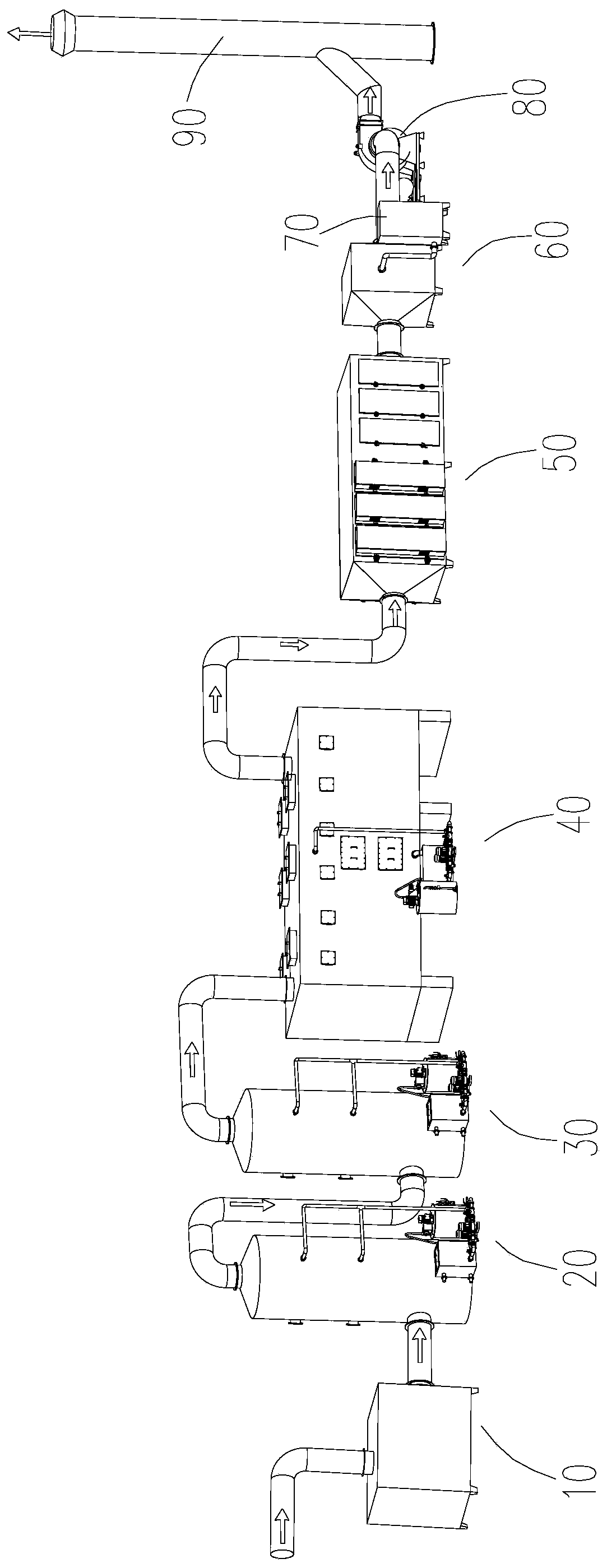
The invention discloses a grease processing industry frying furnace waste gas purification device. According to the device, a chain type dust removing device, a first-stage washing device, a second-stage washing device, a microbial degradation device, a plasma / photocatalysis device, a gas distribution device and an odor controller are sequentially communicated through connecting pipes; and fryingfurnace waste gas is filtered by the chain type dust removing device to remove grease and dust, and the filtered waste gas enters the first-stage washing device and the second-stage washing device, and is subjected to water washing; the frying furnace waste gas after the water washing enters the microbial degradation device, and is subjected to preliminary deodorization; and the frying furnace waste gas after the preliminary deodorization enters the plasma / photocatalysis device, and is subjected to organic matter decomposition, and the obtained waste gas enters the gas distribution device andthe odor controller, and is completely deodorized. According to the invention, the device has good purification effect on waste gas with large air volume, medium and low concentration, high temperature and high protein dust content, and the monitored concentration of the waste gas is far lower than the environmental protection emission standard. The invention further relates to a grease processingindustry frying furnace waste gas purification method.

Description

technical field [0001] The invention relates to waste gas purification, in particular to a frying furnace waste gas purification device in the oil processing industry. Background technique [0002] The pollution factors of exhaust gas from peanut frying furnaces in the oil processing industry are pollutants such as smoke, grease, burnt paste, industrial dust, and odorous gases; and they contain volatile organic compounds such as unsaturated aliphatic hydrocarbons, sesamol, and methyl mercaptan. Exhaust flue gas has a high pollution intensity, a large amount of exhaust gas emission, and complex and changeable pollution components, especially the malodorous components in the exhaust gas are likely to cause relatively large pollution to the surrounding environment and the factory environment, and it is inevitable to disturb the residents. Contents of the invention [0003] In order to overcome the deficiencies of the prior art, the purpose of the present invention is to provi...

Claims


Application Information

Patent Timeline
IPC IPC(8): B01D50/00B01D53/48B01D53/52B01D53/58B01D53/78B01D53/86B01D53/44B01D53/84
CPCB01D53/007B01D53/8687B01D53/78B01D53/58B01D53/52B01D53/48B01D53/84B01D2259/804B01D2257/306B01D2251/304B01D2251/404B01D2251/604B01D2251/106B01D50/20Y02A50/20
Inventor 李云飞周永毅
Owner 紫科装备股份有限公司
Learn More