Eureka AIR delivers breakthrough ideas for toughest innovation challenges, trusted by R&D personnel around the world.

Transfer device, punching system and punching method

A transfer device and punching machine technology, applied in the stamping field, can solve the problems of chaotic on-site management in the production workshop, unable to achieve continuous operation, affecting production efficiency, etc., and achieve the effects of reducing equipment and operation, reducing labor costs, and improving production efficiency.

Active Publication Date: 2020-01-03
KINGCLEAN ELECTRIC +1
View PDF8 Cites 1 Cited by
  • Summary
  • Abstract
  • Description
  • Claims
  • Application Information

AI Technical Summary

Problems solved by technology

In the general stamping process, a product usually needs to be stamped multiple times. Therefore, the traditional stamping factory usually employs multiple operators, one person is responsible for one punching machine, and each person is only responsible for one of the stamping processes, which cannot achieve continuous operation.
When the production process becomes complicated, more personnel are often required, which not only leads to higher production costs, but also seriously affects production efficiency
In addition, when too much manpower is invested, it is easy to lead to confusion in the management of the production workshop site, which is prone to casualties

Method used


Image

  • Transfer device, punching system and punching method
  • Transfer device, punching system and punching method
  • Transfer device, punching system and punching method

Examples


Embodiment Construction

[0028] In order to make the object, technical solution and advantages of the present invention clearer, the present invention will be further described in detail below in conjunction with the accompanying drawings and specific implementation methods. It should be understood that the specific embodiments described here are only used to explain the present invention, and do not limit the protection scope of the present invention.

[0029] It should be noted that when an element is referred to as being “fixed” to another element, it can be directly on the other element or there can also be an intervening element. When an element is referred to as being "connected to" another element, it can be directly connected to the other element or intervening elements may also be present. The terms "vertical," "horizontal," "left," "right," and similar expressions are used herein for purposes of illustration only and are not intended to represent the only embodiments.

[0030] Unless otherw...


PUM


Abstract

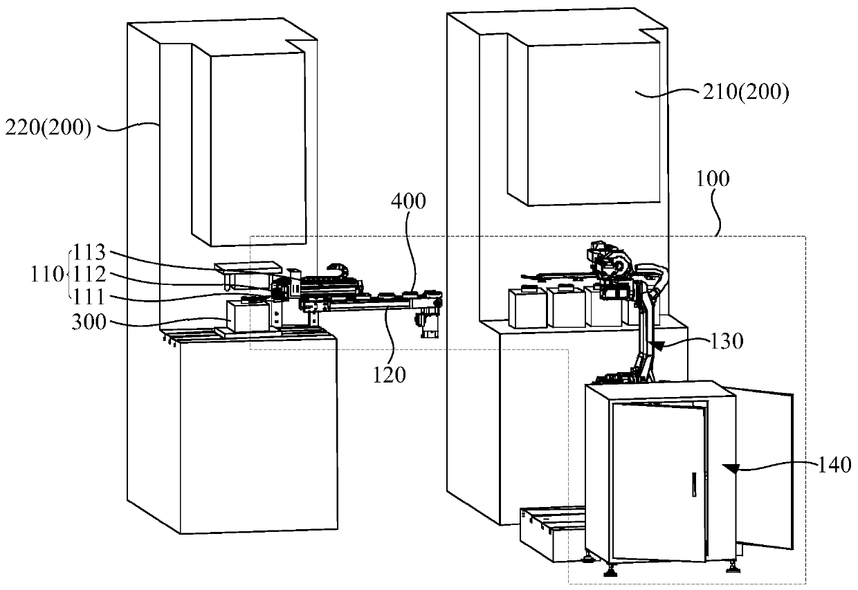
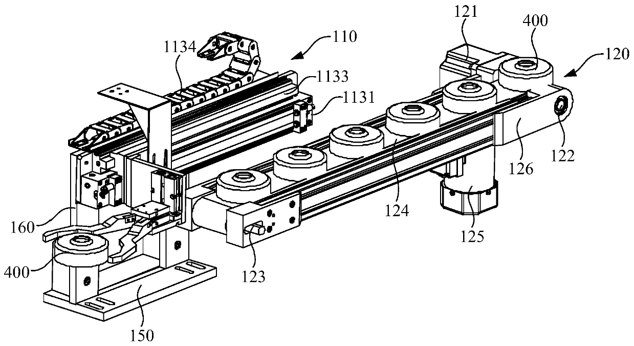
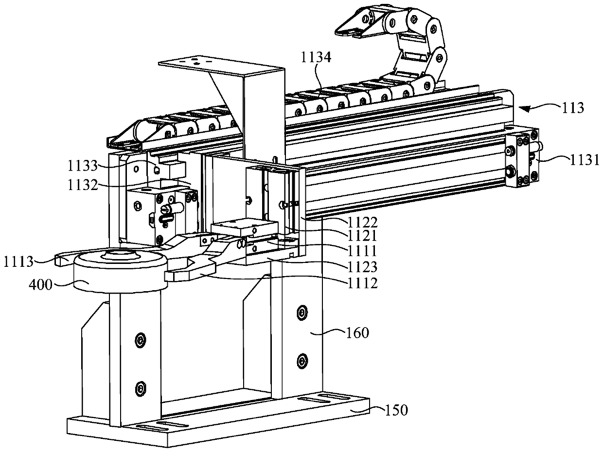
The invention discloses a transfer device, a punching system and a punching method. When a second punching machine completes punching operation, a workpiece is taken out through a first grasping structure; a first moving structure is driven by a second moving structure to move, and the first grasping structure is driven to move to the position above a conveying mechanism in the second direction; then the first grasping structure is made move to the conveying mechanism in the first direction through the first moving structure; the first grasping structure is released so that the workpiece can be placed on the conveying mechanism; the workpiece is conveyed to a first punching machine through the conveying mechanism; and finally, the workpiece is grasped from the conveying mechanism to the first punching machine by means of a mechanical arm, so that operation of automatic taking, automatic transfer and automatic loading of the workpiece is completed, the punching process achieves fully automatic control, the continuous and automatic production of the punching operation is achieved, and the production efficiency is improved; and the staff allocation and operation are reduced, and the personal safety of production workers is ensured.

Description

technical field [0001] The invention relates to the technical field of stamping, in particular to a transfer device, a stamping system and a stamping method. Background technique [0002] Stamping is a forming process in which a workpiece (stamping) of the desired shape and size is obtained by applying external force to a sheet, strip, pipe or profile by a press and a mold to cause plastic deformation or separation. In the general stamping process, a product usually needs to be stamped multiple times. Therefore, the traditional stamping factory usually employs multiple operators, one person is responsible for one punching machine, and each person is only responsible for one of the stamping processes, which cannot achieve continuous operation. . When the production process becomes complicated, more personnel are often required, which not only leads to higher production costs, but also seriously affects production efficiency. In addition, when too much manpower is invested, ...

Claims


Application Information

Patent Timeline
Patent Type & Authority Applications(China)
IPC IPC(8): B21D43/02B21D43/10B21D43/12B21D45/02
CPCB21D43/026B21D43/105B21D43/12B21D45/02
Inventor 倪祖根
Owner KINGCLEAN ELECTRIC
Why Eureka
Eureka Blog
Learn More