LNG gasifier water spraying system and control method
A vaporizer and water spray technology, applied in heat exchanger types, indirect heat exchangers, deicing, etc., can solve the problems of prolonged ice melting time, long time consumption, lack of automatic control of water temperature, etc., to achieve The effect of improving heat exchange efficiency, improving utilization rate, and speeding up ice melting speed
- Summary
- Abstract
- Description
- Claims
- Application Information
AI Technical Summary
Problems solved by technology
Method used
Image
Examples
Embodiment 1
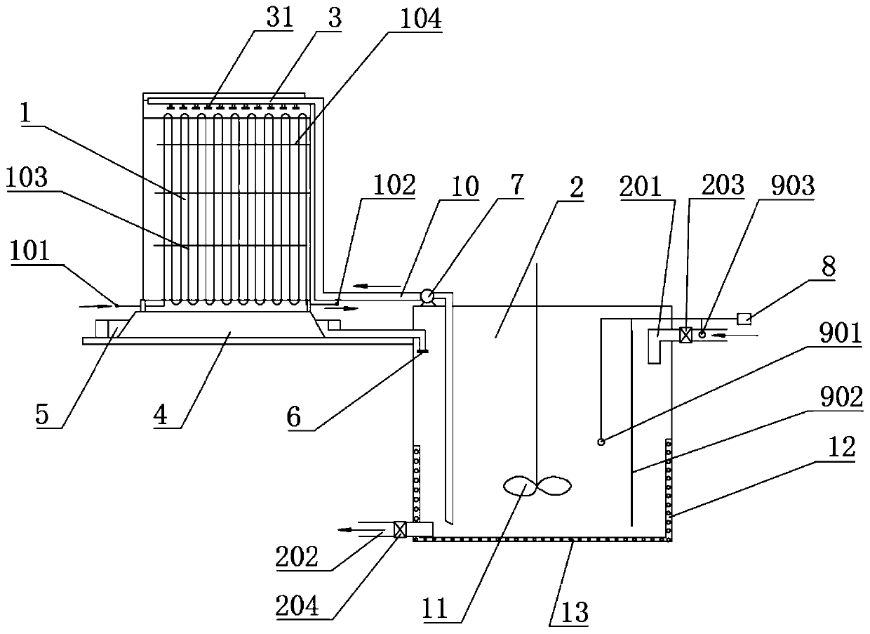
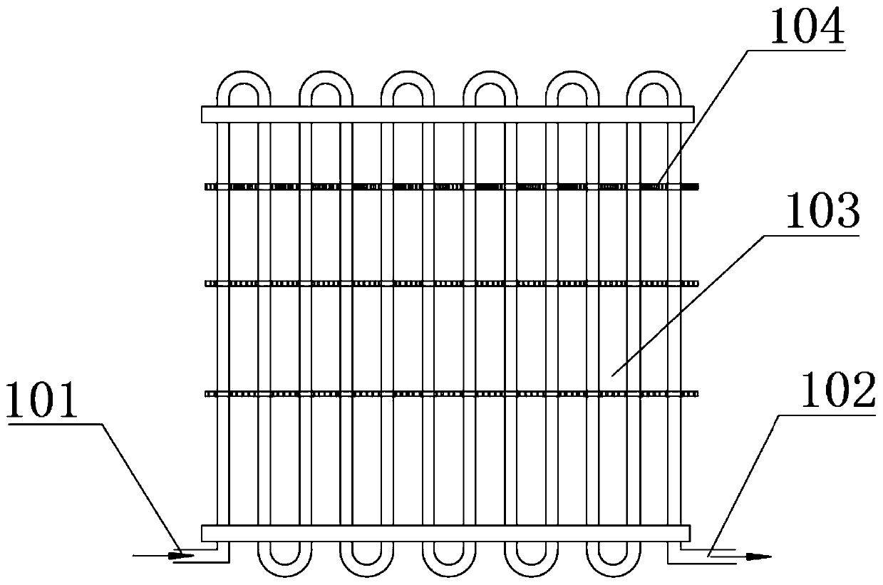
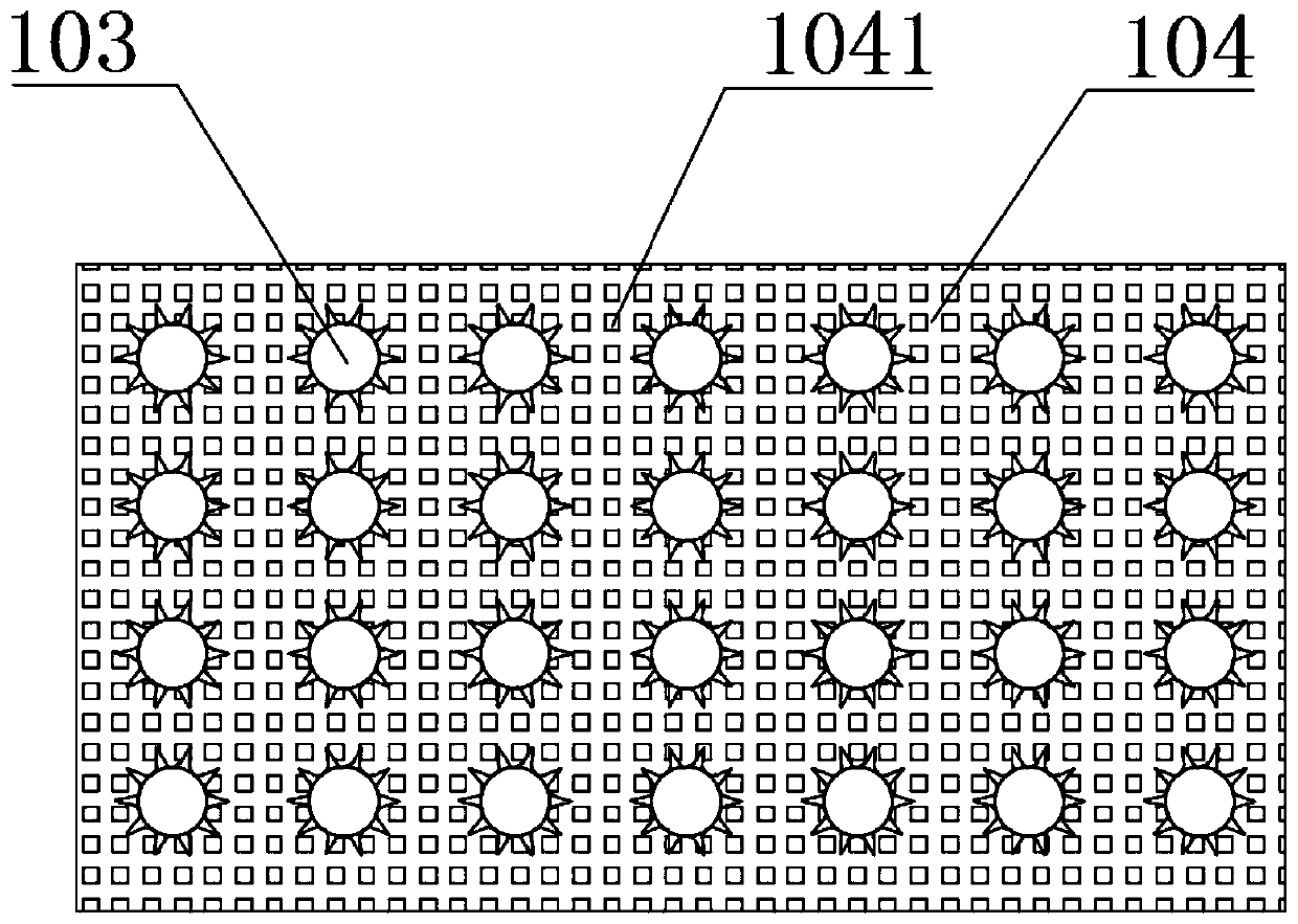
[0047] A kind of LNG vaporizer 1 water spray system, such as figure 1 As shown, it includes an LNG vaporizer 1, a circulating pool 2, a monitoring device 9, a controller 8, and a spray device 3.
[0048] The LNG vaporizer 1 is arranged on a base 4, the base 4 is arranged on the side of the circulating pool 2, a water diversion tank 5 is arranged around the base 4, and the water diversion tank 5 is connected to the The circulating pool 2 is connected, and the spray water flows back to the circulating pool 2 through the water diversion tank 5.
[0049] The upper part of the circulating pool 2 is provided with an inlet pipe 201, and the lower part is provided with a drain pipe 202. The inlet pipe 201 and the drain pipe 202 are respectively provided with valves, which are the inlet pipe valve 203 and the drain pipe valve 204; The side wall and the bottom of the pool 2 are also separately installed with heating devices, which are the side wall heating device 12 and the bottom heating de...
Embodiment 2
[0071] The rest is the same as embodiment 1, the difference is that there is no water blocking layer 104 in the heat exchange tube group, such as Figure 5 , And the fin 1031 on the heat exchange tube 103 is spiral from top to bottom along the outer wall of the heat exchange tube 103, the spiral angle is 45-80°, and the fin 1031 is a thread-like spiral, from top to bottom. The spacing between the lower adjacent spirals increases successively, so that the residence time of the spray water is gradually shortened from top to bottom, and the heat exchange rate is improved.
Embodiment 3
[0073] The rest is the same as in Embodiment 2. The fins 1031 on the heat exchange tube 103 are spirally shaped from top to bottom along the outer wall of the heat exchange tube 103, except that the helix angle is 15-45°. The inner wall of the heat exchange tube 103 is as Image 6 , Figure 7 Smooth inner wall as shown, or as Picture 8 , Picture 9 The spiral shape shown is coaxial with the fin 1031 on the outer wall. The spiral inner wall increases the contact area between the liquefied gas and the inner wall, reduces the flow rate of the liquefied gas, and at the same time generates turbulence, which is beneficial to heat exchange.
PUM
 Abstract
Description
Claims
Application Information
 - R&D
- Intellectual Property
- Life Sciences
- Materials
- Tech Scout
- Unparalleled Data Quality
- Higher Quality Content
- 60% Fewer Hallucinations
Browse by: Latest US Patents, China's latest patents, Technical Efficacy Thesaurus, Application Domain, Technology Topic, Popular Technical Reports.
© 2025 PatSnap. All rights reserved.Legal|Privacy policy|Modern Slavery Act Transparency Statement|Sitemap|About US| Contact US: help@patsnap.com


