
An ultra-thin infrared collimator based on fly-eye lens

A fly-eye lens and collimator technology, which is applied in the field of infrared optics, can solve the problems of large size, difficulty in realizing infrared collimator, and large volume of target source simulation device, and achieve the effect of shortening the focal length of the system

Active Publication Date: 2021-06-01
HARBIN INST OF TECH +1
View PDF0 Cites 0 Cited by
  • Summary
  • Abstract
  • Description
  • Claims
  • Application Information

AI Technical Summary

Problems solved by technology

[0002] The traditional target source simulation device has a large volume and is generally an optical system composed of a set of lenses or mirrors. Larger, unable to realize long-distance parallel light simulation in a small space, and its small F-number infrared collimator is difficult to realize

Method used


Image

  • An ultra-thin infrared collimator based on fly-eye lens
  • An ultra-thin infrared collimator based on fly-eye lens
  • An ultra-thin infrared collimator based on fly-eye lens

Examples


specific Embodiment approach 1

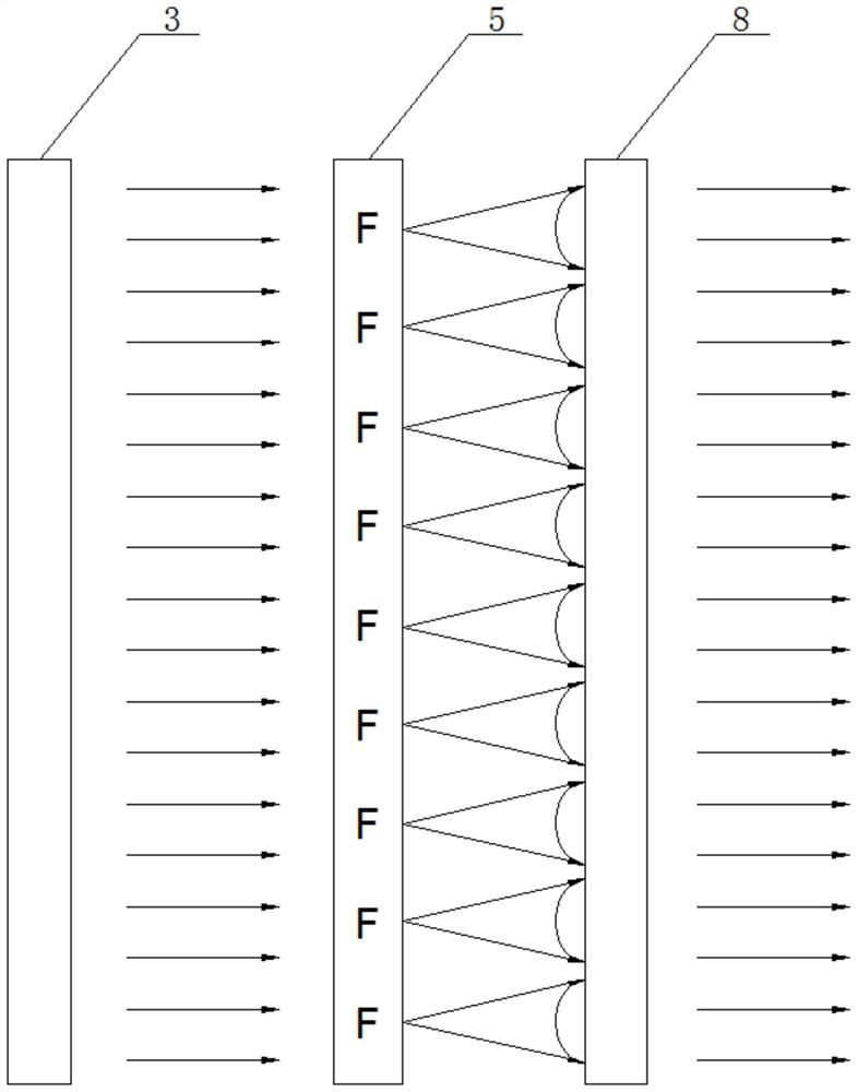
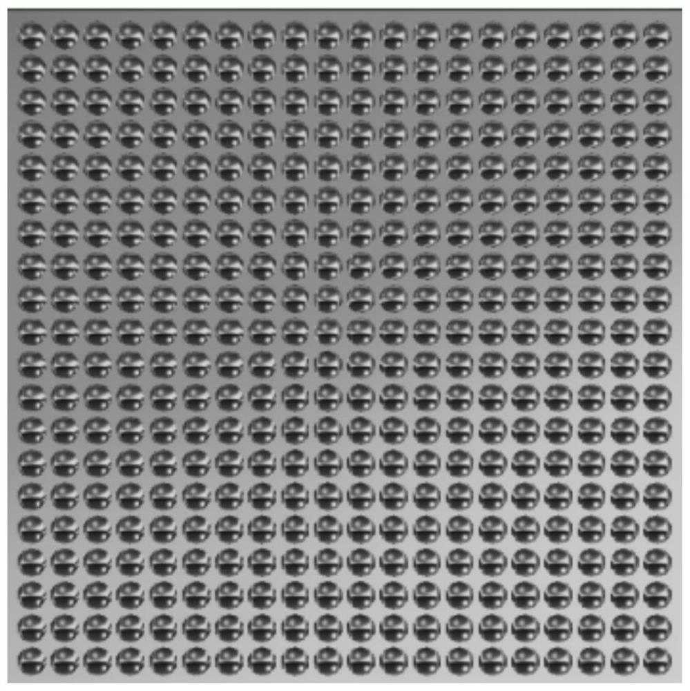
[0025] Specific implementation mode one: as Figure 1-Figure 9 As shown, this embodiment discloses an ultra-thin infrared collimator based on a fly-eye lens, including a light source system, a target lens assembly, a fly-eye lens assembly, a box assembly and an adjustment pad 7, and the box assembly includes a box 4 , a rear cover 1 and a front cover 10, a fly eye lens assembly, a target lens assembly and a light source system are sequentially installed in the box body 4 from front to back, and an adjustment device is tightly installed between the fly eye lens assembly and the target lens assembly Pad 7, the front end of the box body 4 is fixedly equipped with a front cover plate 10, the middle part of the front cover plate 10 is provided with an infrared output window 2, and the rear end of the box body 4 is fixedly equipped with a rear cover plate 1;

[0026] The fly-eye lens 8 in the fly-eye lens assembly is composed of several small lens units in a rectangular array. The t...

specific Embodiment approach 2

[0032] Specific implementation mode two: as Figure 7 As shown, this embodiment is a further description of Embodiment 1. The fly-eye lens assembly includes a fly-eye lens 8, a support seat 6, a partition 11 and a rubber pre-tightening pad 9; the fly-eye lens 8 is fixed In the supporting base 6, the partition 11 is fixed on the front end of the fly-eye lens 8 and the supporting base 6, and the rubber pre-tightening pad 9 is tightly installed between the supporting base 6 and the front cover 10, and the dividing plate 11 The middle part is provided with a light transmission port 12 having the same size as the infrared output window 2 of the front cover 10, and the rubber pre-tightening pad 9 is ring-shaped, and the middle part is provided with a light output port.

specific Embodiment approach 3

[0033] Specific implementation mode three: as Figure 7 As shown, this embodiment is a further description of the first embodiment, the target lens assembly includes the target lens 5 and the second support seat 13; the target lens 5 is fixedly installed in the second support seat 13, and the support Seat two 13 is fixedly connected with casing 4 (by hexagon socket head screw).


PUM

PropertyMeasurementUnit
thicknessaaaaaaaaaa
thicknessaaaaaaaaaa
heightaaaaaaaaaa

Abstract

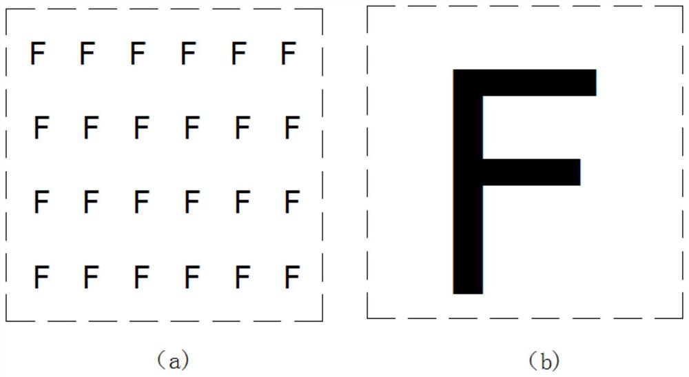
An ultra-thin infrared collimator based on a fly-eye lens belongs to the technical field of infrared optics. The fly eye lens assembly, target lens assembly and light source system are installed in the cabinet in sequence from front to back. The front end of the cabinet is fixed with a front cover, the middle of the front cover is provided with an infrared output window, and the rear of the cabinet is fixed with a rear cover. plate; the fly-eye lens of the fly-eye lens assembly is composed of several small lens units in the form of a rectangular array, and the target image array is engraved on the target lens in the target lens assembly, and the target image array surface is located on the focal plane of 1 times the focal length of the fly-eye lens array surface On the surface of the target image array, several target images 'F' are in one-to-one correspondence with the image planes of several small lens units on the fly-eye lens array, and the targets are consistent. The focal points of several small lens units in the fly-eye lens array Coincides with the center of several target images 'F' in the target lens image array. The invention is used for detection and identification of infrared optical targets.

Description

technical field [0001] The invention relates to an infrared collimator based on a fly-eye lens, in particular to an ultra-thin infrared collimator based on a fly-eye lens and an array target lens, and belongs to the technical field of infrared optics. Background technique [0002] The traditional target source simulation device has a large volume. It is generally an optical system composed of a set of lenses or mirrors. Larger, it cannot realize long-distance parallel light simulation in a small space, and its small F-number infrared collimator is difficult to realize. Contents of the invention [0003] The object of the present invention is to solve the problems existing in the above-mentioned prior art, and provide an ultra-thin infrared collimator based on a fly-eye lens. Necessary equipment for tuning. [0004] As an infrared target source simulation device, the present invention can be widely used in the detection and identification of infrared optical targets, to d...

Claims


Application Information

Patent Timeline
Patent Type & Authority Patents(China)
IPC IPC(8): G02B27/30G01V13/00G01V8/10
CPCG01V8/10G01V13/00G02B27/30
Inventor 郭鑫民康为民杨振张建隆张建军高金红高清京
Owner HARBIN INST OF TECH
Learn More