
Resistance-inductance type DC current limiting apparatus and method based on magnetic coupling enhancement characteristics

A technology of a current limiting device and a current limiting method, which is applied to emergency protection circuit devices, circuit devices, emergency protection circuit devices, etc. for limiting overcurrent/overvoltage, and can solve the difficulty of short-circuit current limitation and the rapid rise of fault current and other problems, to achieve the effect of good current limiting effect, fast response speed of current limiting, and small impact

Active Publication Date: 2020-01-03
TIANJIN UNIV
View PDF10 Cites 3 Cited by
  • Summary
  • Abstract
  • Description
  • Claims
  • Application Information

AI Technical Summary

Problems solved by technology

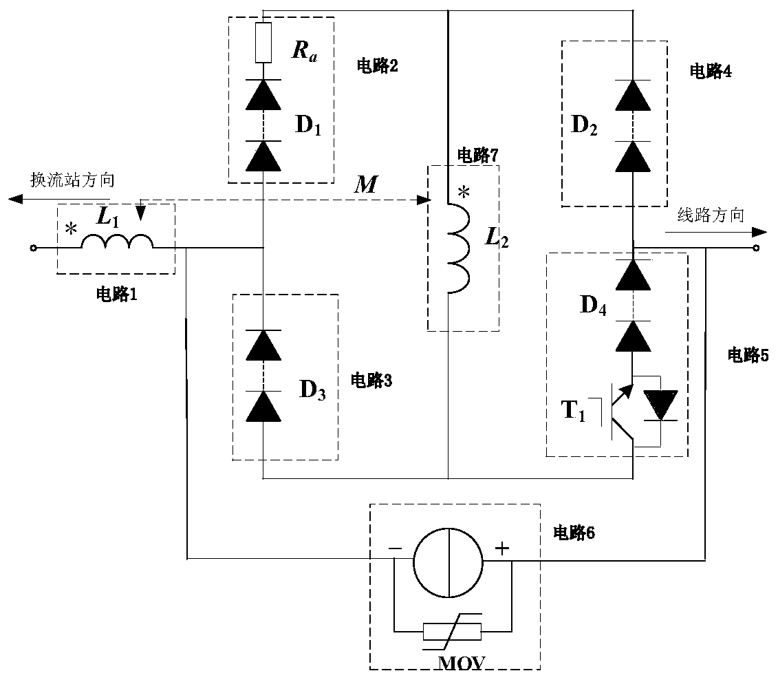
[0003] In order to solve the problem that the fault current rises too fast after the DC line fault occurs and the short-circuit current is difficult to limit, the present invention proposes a resistance-inductive DC current limiting device and method based on magnetic coupling enhancement characteristics to realize common current limiting of inductors and resistors Resistance-sensing DC current limiting function

Method used


Image

  • Resistance-inductance type DC current limiting apparatus and method based on magnetic coupling enhancement characteristics
  • Resistance-inductance type DC current limiting apparatus and method based on magnetic coupling enhancement characteristics
  • Resistance-inductance type DC current limiting apparatus and method based on magnetic coupling enhancement characteristics

Examples


Embodiment Construction

[0016] The technical solution of the present invention will be described in detail below in conjunction with the accompanying drawings and embodiments. The embodiment is only an example, and is not intended to limit the technical solution of the present invention.

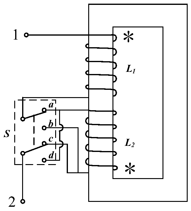
[0017] Such as figure 1 As shown, it is a schematic diagram of a resistive-inductive DC current limiting method based on magnetic coupling enhancement characteristics of the present invention. The current limiting method consists of a switching device S, a pair of fully coupled inductance coils L wound on the same iron core with equal self-inductance 1 , L 2 accomplish. During normal operation, the double-pole double-throw switch S is closed at the b-side and d-side, and the line current flows in from the different-named ends of the two coupled inductor coils, the magnetic flux cancels each other, and the equivalent inductance of the current limiter is almost 0; short circuit After a fault occurs, the switch S ...


PUM


Abstract

The invention discloses a resistance-inductance type DC current limiting apparatus and method based on magnetic coupling enhancement characteristics. The current limiting apparatus comprises a switching device S, a resistive element, and a pair of full-coupling inductance coils L1 and L2 wound on the same iron core and having equal self-inductance. When the double-pole double-throw switch S is closed at an end b and an end d, the apparatus is in an inductance current-limiting normal operation state. When the switch S is switched to an end a and an end c, the apparatus is in an inductance current-limiting short-circuit fault state. The resistive element is arranged on an end-a inductance coil side of the switch S and is used for realizing resistance-inductance common DC current limiting. Compared with the prior art, the apparatus and the method have the characteristics of good current limiting effect, capability of simultaneously inputting inductance and resistance for current limiting,and high recovery speed after a fault.

Description

technical field [0001] The invention relates to the field of power system protection, in particular to a resistive-inductive direct current limiting method. Background technique [0002] The DC fault protection of the flexible DC system is a key technology in the development of the DC system. In order to ensure the safe and reliable operation of the DC system, the DC circuit breaker of the flexible DC system needs to act quickly within a few milliseconds of the DC fault, and reliably cut off the fault line. It is difficult for the circuit breaker to quickly remove the line fault, so a fault current limiter needs to be connected in series to limit the rising speed and amplitude of the fault current, leaving enough margin for the DC circuit breaker to cut off the fault line. Although the DC fault current limiter technology is constantly developing, the existing DC current limiters still have shortcomings such as high cost, slow response speed, and poor current limiting effect...

Claims


Application Information

Patent Timeline
Patent Type & Authority Applications(China)
IPC IPC(8): H02H9/02H02H7/26
CPCH02H7/268H02H9/02
Inventor 李斌杨嵩
Owner TIANJIN UNIV
Learn More