Clock synchronization method and device, computer storage medium and electronic equipment

A clock synchronization and time correction technology, applied in the field of automation technology, can solve the problems of client local time correction, difficult to be strictly consistent with delay, and not used.

Active Publication Date: 2020-01-03
北京和利时系统集成有限公司
View PDF10 Cites 12 Cited by
  • Summary
  • Abstract
  • Description
  • Claims
  • Application Information

AI Technical Summary

Problems solved by technology

[0004] Although the local time of the client can be corrected based on NTP, in actual industrial automation production, there are the following problems: 1. Many network devices and communication media using serial ports do not support NTP; 2. Traditional industrial automation communication protocols are basically NTP is not used; for example: 101 and 103 protocols only make simple corrections to the transmission delay according to the theoretical serial port transmission time (the length of the message divided by the transmission speed); 104 protocols do not correct the local time of the client; It is a serial communication protocol published by programmable logic controller (PLC) communication, which is a commonly used connection method between industrial electronic equipment), field bus (Profibus) and other protocols themselves do not restrict the specific timing format, which is mainly determined by each application The manufacturer independently formulates the format and specification of the school time message. Generally, the slave station corrects the local time of the client according to the time information received from the master station.
3. NTP assumes that the transmission delay in both directions of the network is the same, but in the actual environment, the two-way delay is difficult to be strictly consistent. When a large delay error occurs in the long-term communication process, it will cause the clock of the client device to be corrected. jitter

Method used


Image

  • Clock synchronization method and device, computer storage medium and electronic equipment
  • Clock synchronization method and device, computer storage medium and electronic equipment
  • Clock synchronization method and device, computer storage medium and electronic equipment

Examples


Embodiment Construction

[0048] In order to make the object, technical solution and advantages of the present invention more clear, the embodiments of the present invention will be described in detail below in conjunction with the accompanying drawings. It should be noted that, in the case of no conflict, the embodiments in the present application and the features in the embodiments can be combined arbitrarily with each other.

[0049] The steps shown in the flowcharts of the figures may be performed in a computer system, such as a set of computer-executable instructions. Also, although a logical order is shown in the flowcharts, in some cases the steps shown or described may be performed in an order different from that shown or described herein.

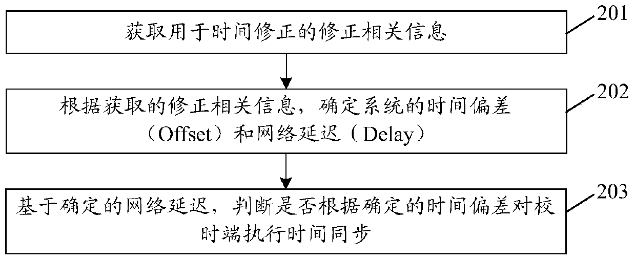
[0050] figure 2 It is a flowchart of a method for clock synchronization in an embodiment of the present invention, such as figure 2 shown, including:

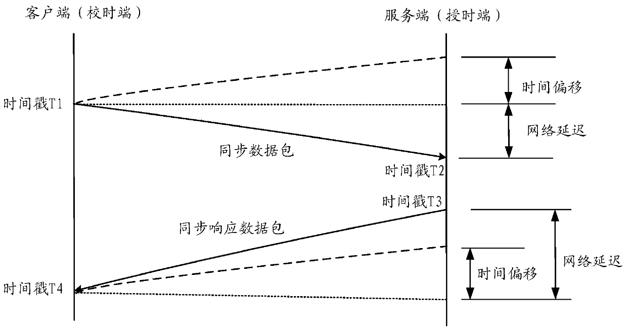
[0051] Step 201, obtaining correction-related information for time correction;

[0052] Wherein, the ...


PUM


Abstract

The invention discloses a clock synchronization method and device, a computer storage medium and electronic equipment, and the method comprises the steps: achieving the determination of time deviationthrough the receiving and transmitting of a time stamp of a conventional message, and judging whether to carry out the time synchronization or not according to the time deviation through network delay. Furthermore, the excessive delay jitter is judged through the network delay, so that the influence of the excessive delay jitter on the time correction of the time service end is avoided.

Description

technical field [0001] This article involves but is not limited to automation technology, especially a clock synchronization method, device, computer storage medium and electronic equipment. Background technique [0002] In occasions that require precise time synchronization, such as comprehensive monitoring, power communication, factory (distributed control system) DCS, etc., it is difficult to meet the accuracy requirements of time synchronization only by the clock signal provided by the computer itself. According to statistics, more than 90% of the computer time deviates from the international standard time by more than 1 minute. This is because the clock signal of the computer comes from its own simple crystal oscillator. After time correction, there is usually a time drift of a few seconds per day. Logs, alarms, time sequence records (SOE) in industrial automation systems all use time as the first sorting element, especially in the process of fault analysis, wrong time...

Claims


Application Information

Patent Timeline
Patent Type & Authority Applications(China)
IPC IPC(8): H04J3/06
CPCH04J3/0667H04J3/0682
Inventor 贺学文
Owner 北京和利时系统集成有限公司
Why Eureka
Try Eureka