
Piezoelectric MEMS microphone

A microphone and piezoelectric technology, which is applied in the field of piezoelectric MEMS microphones, can solve problems such as the reduction of resonance frequency, the increase of piezoelectric MEMS noise, and the inability to meet user needs, and achieve the effect of reducing noise and improving resonance frequency

Active Publication Date: 2020-01-03
AAC ACOUSTIC TECH (SHENZHEN) CO LTD
View PDF7 Cites 7 Cited by
  • Summary
  • Abstract
  • Description
  • Claims
  • Application Information

AI Technical Summary

Problems solved by technology

[0004] However, due to the residual stress of the piezoelectric MEMS microphone in the process, the diaphragm will undergo deformations such as edge warping and involution to varying degrees, resulting in differences in the attenuation of the entire diaphragm at low frequencies, thereby significantly reducing its resonance frequency (< 10kHz), the noise of the entire piezoelectric MEMS increases, which cannot meet user needs

Method used


Image

  • Piezoelectric MEMS microphone
  • Piezoelectric MEMS microphone
  • Piezoelectric MEMS microphone

Examples


Embodiment Construction

[0029] The present invention will be further described below in conjunction with the accompanying drawings and embodiments.

[0030] It should be noted that all directional indications (such as up, down, inside, outside, top, bottom...) in the embodiments of the present invention are only used to explain the relationship between the components in a certain posture (as shown in the drawings). If the specific posture changes, the directional indication will also change accordingly.

[0031] It should also be noted that when an element is referred to as being “fixed” or “disposed on” another element, the element may be directly on the other element or there may be an intervening element at the same time. When an element is referred to as being "connected to" another element, it can be directly connected to the other element or intervening elements may also be present.

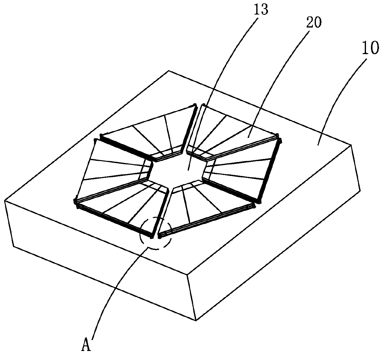
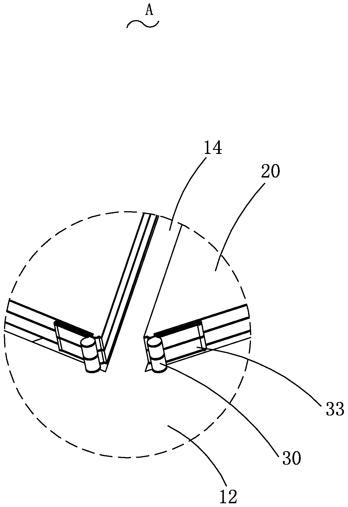
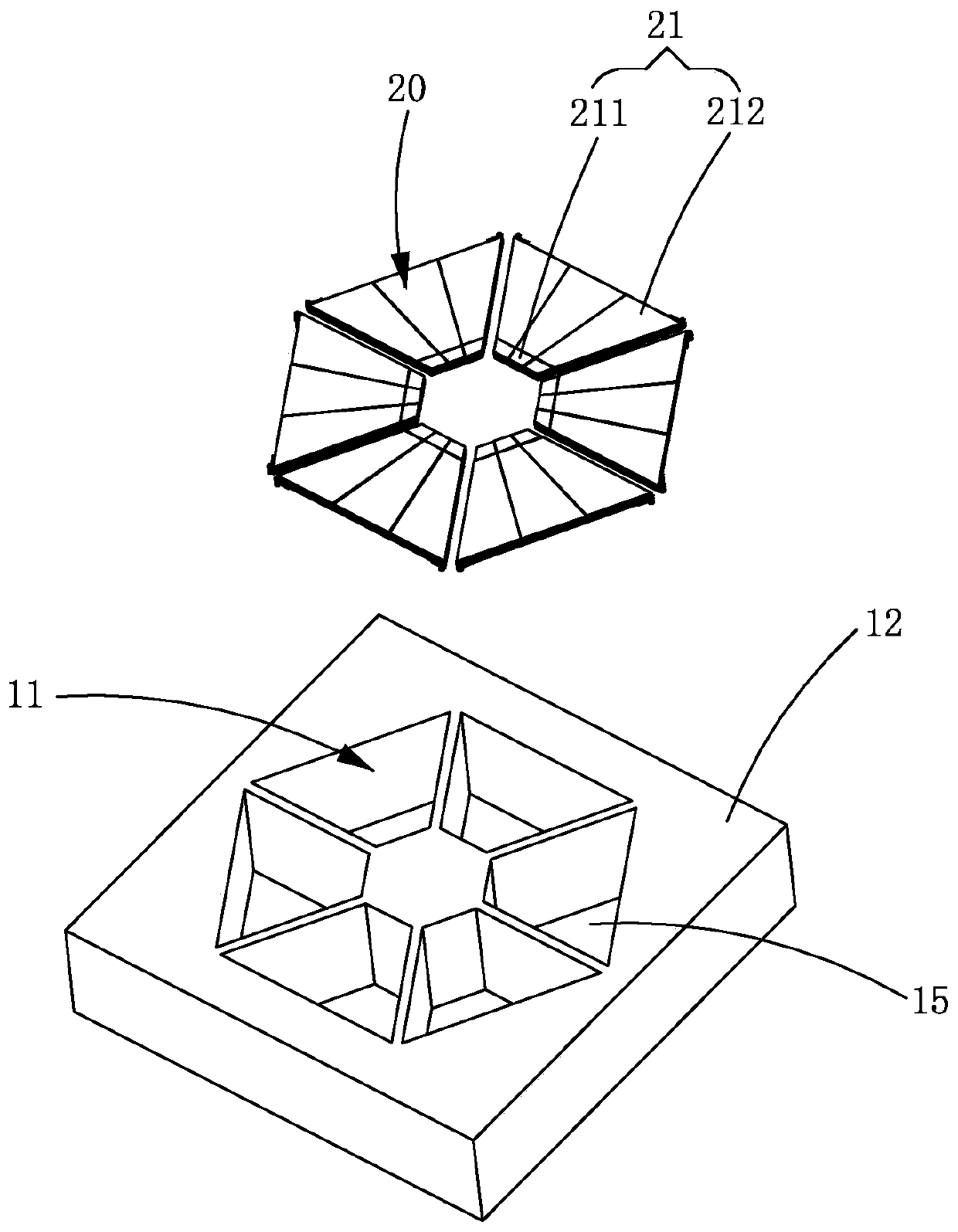
[0032] see Figure 1 to Figure 8 , the embodiment of the present invention provides a piezoelectric MEMS micr...


PUM


Abstract

The invention provides a piezoelectric MEMS microphone, comprising a substrate with a cavity, a piezoelectric vibrating diaphragm arranged on the substrate, and a constraint piece connected with the substrate and the piezoelectric vibrating diaphragm, wherein the substrate comprises an annular base defining a cavity, and a supporting column arranged in the cavity and spaced from the annular base;the piezoelectric vibrating diaphragm comprises a plurality of diaphragms; each diaphragm comprises a fixed end connected with the supporting column and a free end suspended above the cavity; and oneend of the constraint piece is fixedly connected with the free end, and the other end of the constraint piece is connected with the part, not connected with the fixed end, of the substrate. For the piezoelectric MEMS microphone, under the action of sound pressure, the free end vibrates, and the piezoelectric vibrating diaphragm close to the fixed end can generate a voltage signal, and a restraining piece is arranged between the substrate and the piezoelectric vibrating diaphragm and can restrain the deformation of the diaphragm, so that the resonant frequency of the piezoelectric vibrating diaphragm is improved, and the noise of the whole piezoelectric MEMS microphone is reduced.

Description

【Technical field】 [0001] The invention relates to the technical field of acoustic-electric conversion devices, in particular to a piezoelectric MEMS microphone. 【Background technique】 [0002] MEMS microphone is an electro-acoustic transducer made by micromachining technology, which has the characteristics of small size, good frequency response characteristics, and low noise. With the development of electronic devices towards miniaturization and thinning, MEMS microphones are more and more widely used in these devices. [0003] At present, MEMS microphones are mainly divided into capacitive MEMS microphones and piezoelectric MEMS microphones. Piezoelectric MEMS microphones have many advantages over traditional capacitive MEMS microphones, including dust resistance, water resistance, and higher maximum output sound pressure (AOP). Different from the piezoelectric diaphragm structure of the capacitive microphone, the piezoelectric diaphragm of the piezoelectric MEMS micropho...

Claims


Application Information

Patent Timeline
Patent Type & Authority Applications(China)
IPC IPC(8): H04R19/04
CPCH04R19/04H04R17/02H04R2201/003B81B3/007B81B2201/0257B81B2203/0127B81B2203/0315H04R7/04H04R7/24
Inventor 段炼张睿陈志远
Owner AAC ACOUSTIC TECH (SHENZHEN) CO LTD
Learn More