
Automatic control device for punching machine production line

An automatic control device and production line technology, applied in the field of stamping and forming, can solve the problems of high noise in the working environment, many safety accidents, poor quality stability, etc., and achieve the effect of facilitating processing and production and preventing breakage

Pending Publication Date: 2020-01-07
大冶市一际通智能科技有限公司
View PDF0 Cites 2 Cited by
  • Summary
  • Abstract
  • Description
  • Claims
  • Application Information

AI Technical Summary

Problems solved by technology

[0002] A punching machine is a stamping press. In national production, the stamping process saves materials and energy compared with traditional machining, has high efficiency, does not require high technical requirements for operators, and can make mechanical parts through various mold applications. The advantages of products that cannot be achieved by processing, so its use is becoming more and more extensive. Discontinuous stamping production is mainly based on manual loading and unloading and operating machine tools, which has low automation, many safety accidents, high noise in the working environment, and stable quality. Problems such as poor performance are affected by the rising labor costs, resulting in increased labor costs

Method used


Image

  • Automatic control device for punching machine production line
  • Automatic control device for punching machine production line
  • Automatic control device for punching machine production line

Examples


Embodiment Construction

[0022] The following will clearly and completely describe the technical solutions in the embodiments of the present invention with reference to the accompanying drawings in the embodiments of the present invention. Obviously, the described embodiments are only some, not all, embodiments of the present invention. Based on the embodiments of the present invention, all other embodiments obtained by persons of ordinary skill in the art without making creative efforts belong to the protection scope of the present invention.

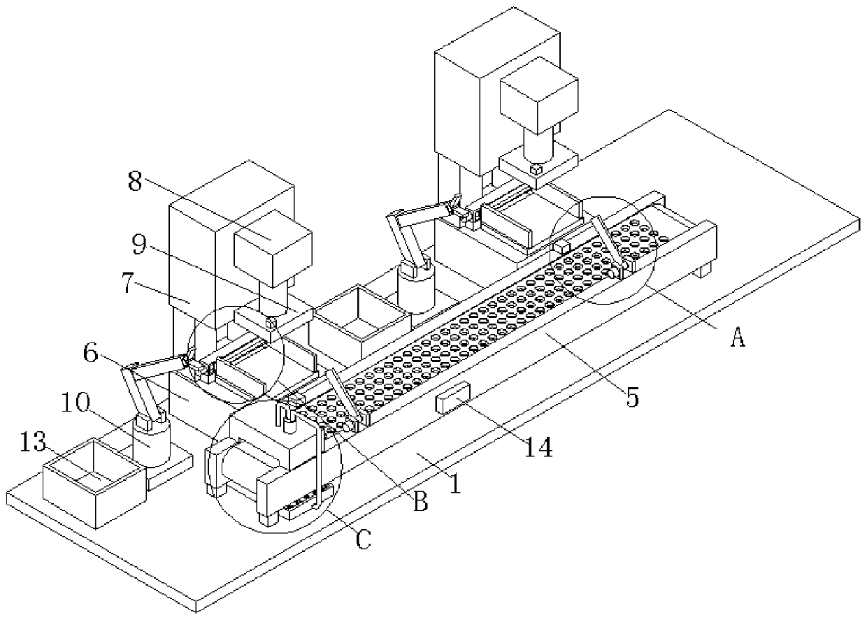
[0023] see Figure 1-4 , the present invention provides a technical solution: an automatic control device for a punch press production line, including a bottom plate 1, a feeding unit 2, an adjustment unit 3 and a belt conveyor 5;

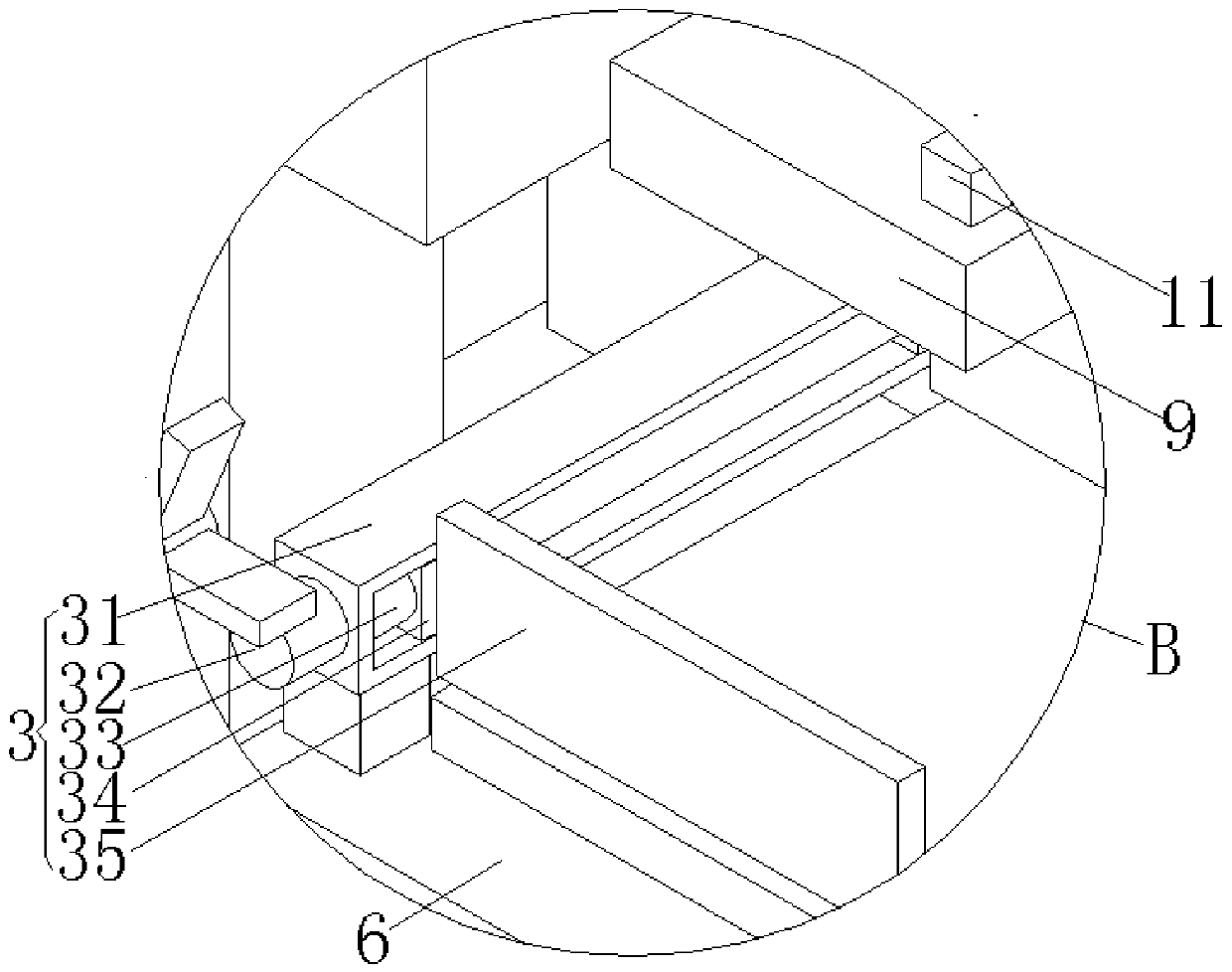
[0024] Bottom plate 1: a belt conveyor 5 is provided on the front side of the upper surface of the bottom plate 1, and a cleaning unit 4 is provided on the left end of the upper surface of the belt conveyor 5. The cleaning unit 4 i...


PUM


Abstract

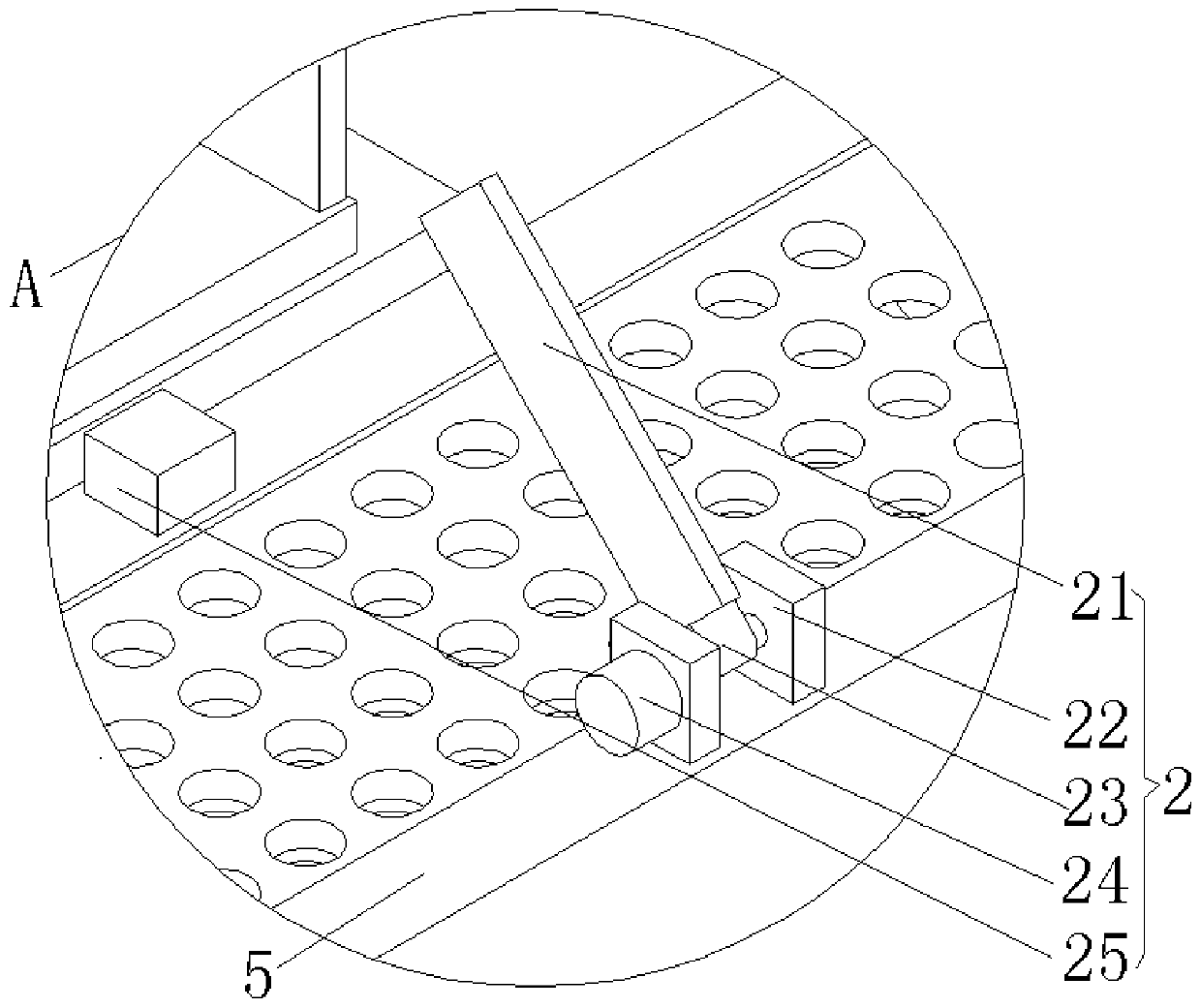
The invention discloses an automatic control device for a punching machine production line. The automatic control device for the punching machine production line comprises a bottom plate, a feeding unit, an adjusting unit and a belt conveyor, wherein the belt conveyor is arranged on the front side of the upper surface of the bottom plate, a cleaning unit is arranged at the left end of the upper surface of the belt conveyor, the feeding unit comprises a baffle, fixing plates, a fixing head, a first motor and a laser sensor, wherein two fixing plates are correspondingly arranged on the front side of the upper surface of the belt conveyor, the first motor is arranged on the left side of the fixing plate on the left side, a rotating shaft is connected between two fixing plates in a rotating mode, the left end of the rotating shaft is connected with the output shaft of the first motor, the outer side of the rotating shaft is fixedly connected with one end of a connecting head, the baffle isarranged at the other end of the connecting head, the laser sensor is arranged on the rear side of the upper surface of the belt conveyor, and the laser sensor corresponds to the front and back of the baffle. According to the automatic control device for the punching machine production line, the automation degree is high, the production is safe, and the labor cost is effectively reduced.

Description

technical field [0001] The invention relates to the technical field of punching and forming, in particular to an automatic control device for a punch press production line. Background technique [0002] A punching machine is a stamping press. In national production, the stamping process saves materials and energy compared with traditional machining, has high efficiency, does not require high technical requirements for operators, and can make mechanical parts through various mold applications. The advantages of products that cannot be achieved by processing, so its use is becoming more and more extensive. Discontinuous stamping production is mainly based on manual loading and unloading and operating machine tools, which has low automation, many safety accidents, high noise in the working environment, and stable quality. Problems such as poor quality are affected by the rising labor costs, resulting in increased labor costs. Contents of the invention [0003] The technical ...

Claims


Application Information

Patent Timeline
IPC IPC(8): B21D43/02B21D43/10B21D43/12B21D43/20B21D45/02B08B3/02B08B13/00
CPCB08B3/022B08B13/00B21D43/026B21D43/027B21D43/105B21D43/12B21D43/20B21D45/02
Inventor 王飞
Owner 大冶市一际通智能科技有限公司
Learn More