Steel winding and conveying device
A technology for conveying equipment and steel coils, which is applied in the field of steel processing, and can solve problems such as the influence of the quality of the rim, the deformation of the rim, and the influence of steel coiling, etc., and achieve the effect of excellent quality of the rim
- Summary
- Abstract
- Description
- Claims
- Application Information
AI Technical Summary
Problems solved by technology
Method used
Image

Examples
Embodiment 1
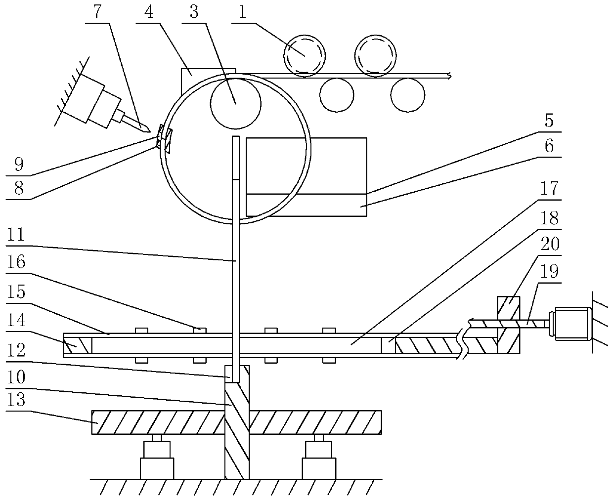
[0026] Embodiment 1 is basically as attached figure 2 , 3 Shown: as figure 2 The steel winding transmission equipment shown includes a frame, a transmission mechanism, a winding mechanism and a cutting mechanism. The transmission mechanism includes several groups of transmission wheels that are rotatably arranged on the frame. figure 2 Only two sets of transmission wheels are shown in the figure, each set of transmission wheels includes an upper transmission wheel 1 and a lower transmission wheel, the upper transmission wheel 1 is in the shape of "I", and the ends of the upper transmission wheel 1 and the lower transmission wheel are welded with pin shafts , the frame is provided with a hole, and the pin shaft is inserted into the hole and rotated to be arranged in the hole.
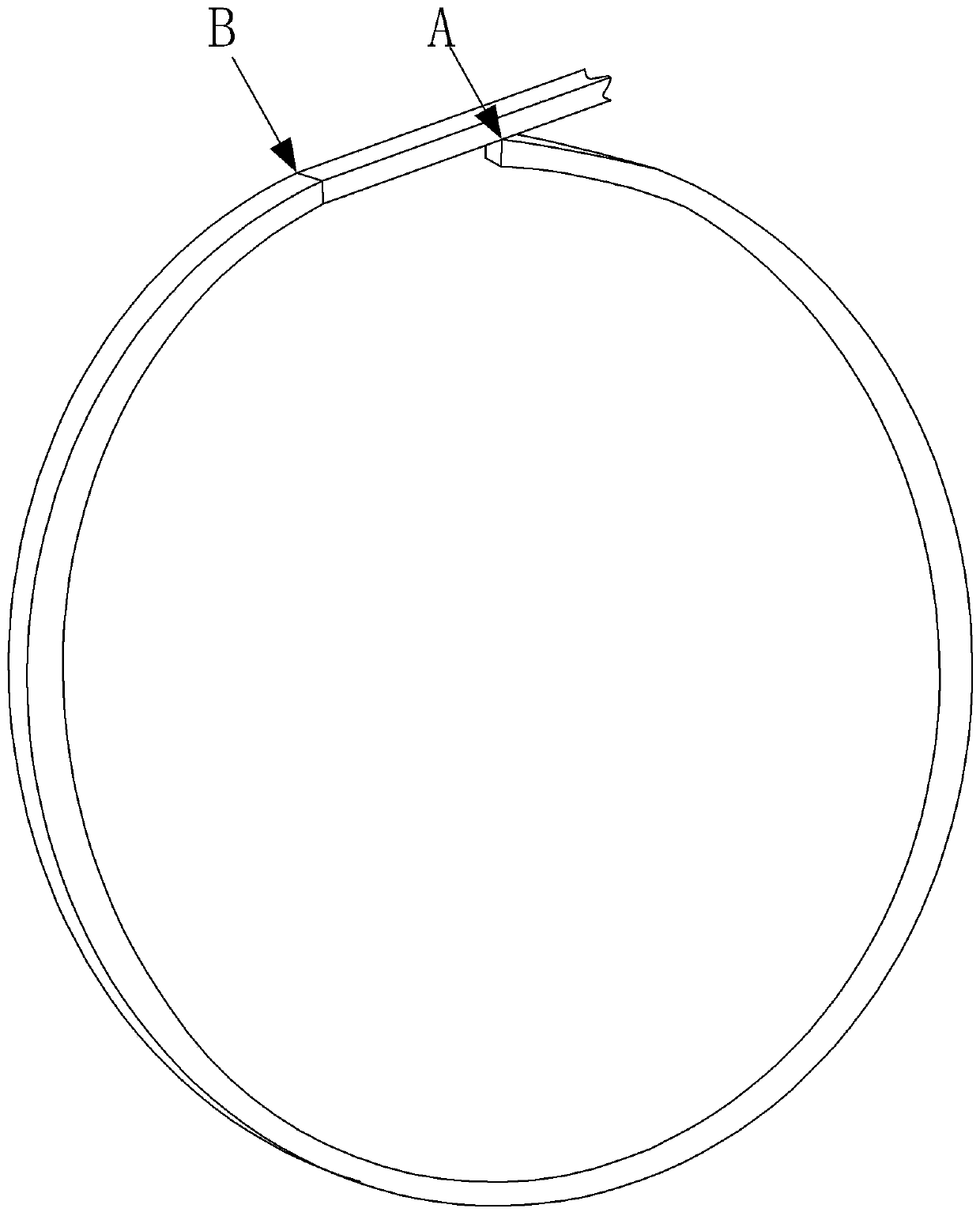
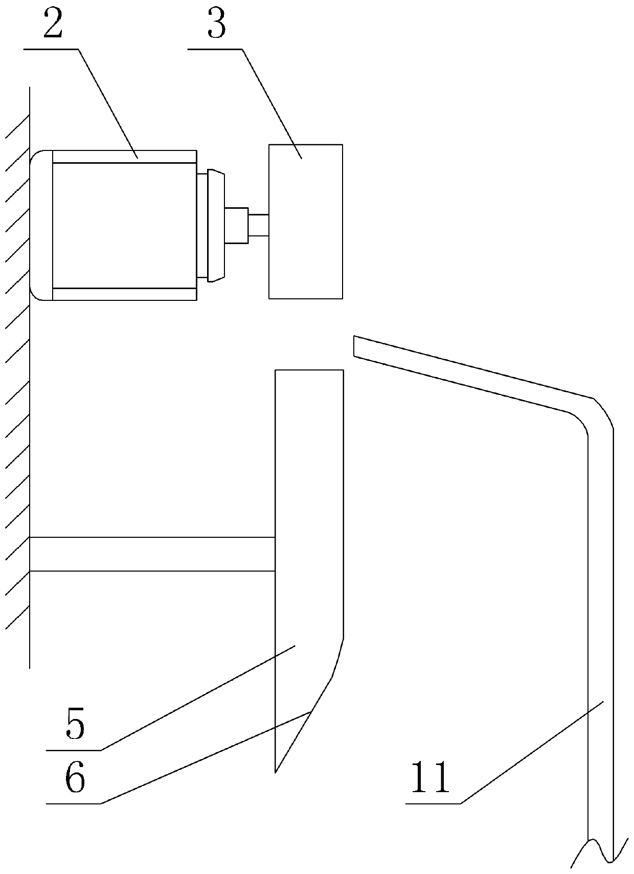
[0027] The winding mechanism includes a stepper motor 2, a winding roller 3, a winding block 4 and a dislocation block 5, such as image 3 As shown, the stepper motor 2 is fixedly installed on the ...
Embodiment 2
[0030] On the basis of embodiment 1, embodiment 2 also includes a material guide rod and a correction and reclaiming mechanism. Such as figure 2 As shown, the material guide bar includes a stabilizing bar 10 and a movable bar 11, the lower end of the stabilizing bar 10 is fixedly connected with the ground by bolts, and the upper end of the stabilizing bar 10 is opened as Figure 4 The connecting groove 12 shown, the side wall of the connecting groove 12 is fastened with an arc-shaped magnet; image 3 Shown, movable rod 11 is " 7 " font, and movable rod 11 is made of iron, as figure 2 As shown, the lower end of the movable rod 11 is fixedly connected with the stable rod 10 through a magnet.
[0031] Such as figure 2 As shown, the correcting and retrieving mechanism includes a pressing plate 13, a pressure-stopping plate 14, two slide rails 15, a push-pull unit and a lifting unit; The strip slide rails 15 are located on the same horizontal plane, and the open ends of the ...
PUM
 Abstract
Description
Claims
Application Information
 - R&D
- Intellectual Property
- Life Sciences
- Materials
- Tech Scout
- Unparalleled Data Quality
- Higher Quality Content
- 60% Fewer Hallucinations
Browse by: Latest US Patents, China's latest patents, Technical Efficacy Thesaurus, Application Domain, Technology Topic, Popular Technical Reports.
© 2025 PatSnap. All rights reserved.Legal|Privacy policy|Modern Slavery Act Transparency Statement|Sitemap|About US| Contact US: help@patsnap.com