
The Method of Improving the Anti-cavitation Performance of the Impeller

An impeller and performance technology, applied in the field of anti-cavitation centrifugal impeller, can solve problems such as increase of absolute and relative velocity of liquid flow, uneven distribution of impeller inlet velocity, deterioration of pump cavitation performance, etc.

Active Publication Date: 2020-12-11
CHENGDU KAITIAN ELECTRONICS
View PDF9 Cites 0 Cited by
  • Summary
  • Abstract
  • Description
  • Claims
  • Application Information

AI Technical Summary

Problems solved by technology

[0003] The cross-section of the centrifugal pump impeller is generally an airfoil. When cavitation occurs, the cavitation is very complex, including attached cavitation, free cavitation (cloud cavitation), etc., and the cavitation flow is extremely unstable.
The liquid flow at the inlet of the impeller is affected by the centrifugal force at the turn, and the pressure of the liquid flow near the front cover is low and the flow velocity is high, resulting in uneven distribution of the impeller inlet velocity.
The throat area of ​​the vane inlet also has a great influence on the cavitation performance of the pump. If the throat area of ​​the vane inlet is too small, the absolute velocity and relative velocity of the liquid flow at the vane inlet will increase, thereby increasing the displacement of the liquid flow and making the The cavitation performance of the pump deteriorates

Method used


Image

  • The Method of Improving the Anti-cavitation Performance of the Impeller
  • The Method of Improving the Anti-cavitation Performance of the Impeller
  • The Method of Improving the Anti-cavitation Performance of the Impeller

Examples


Embodiment Construction

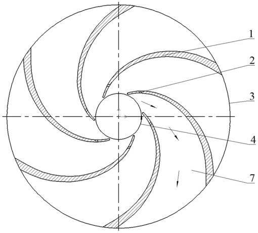
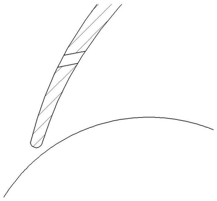
[0017] refer to figure 1 . According to the present invention, an inducer is installed in front of the first-stage impeller of the pump, and the long blade 1 with a slot fixedly connected to the impeller is surrounded by an Archimedes spiral, and the head of the long blade 1 is rounded, and the distance from the head is A gap 2 with a width of 1mm to 2mm gradually increasing from the inside to the outside is set at the position. The direction of the gap 2 is from the high pressure side to the low pressure side, and the angle between the gap 2 and the flow direction is an acute angle; Calculate the throat area of ​​the blade inlet and the cross-sectional area of ​​the impeller inlet with the angle of attack of the blade inlet, and set the ratio X of the throat area of ​​the blade inlet to the cross-sectional area of ​​the impeller inlet to be at least greater than 0.28; then grind the working surface of the blade inlet before assembly, so that The blade inlet is thinned and ma...


PUM


Abstract

The invention discloses a method for improving cavitation resistance of an impeller, and the method aims to improve cavitation performance of a front-stage impeller of a multi-stage pump and performance under a large-flow working condition of the multi-stage pump. The method is realized through the following technical scheme: additionally arranging an induce wheel in front of the front-stage impeller of the pump, fixedly connecting a long blade with a seam in a mode that an archimedes spiral surrounds the impeller, forming a 1mm-2mm seam which is gradually increased on a position away from thehead of the long blade, and enabling the direction of the seam to form an included angle, which is an acute angle, with the flowing direction; calculating the area of an inlet throat part of the blade and the area of the inlet section of the impeller according to an impeller inlet diameter, width, a blade inlet liquid-flow angle and an inlet attack angle, setting a ratio of the inlet throat partof the blade to the area of the inlet section of the impeller to be greater than 0.28; and grinding the working surface of the blade inlet, enabling the working surface to be similar to a streamline form to reduce impact while liquid flow enters the blade, increasing the inlet attack angle of the blade to increase over-flow area of the blade inlet and to reduce extrusion of the blade while an inlet working surface of the blade is grinded.

Description

technical field [0001] The invention relates to an anti-cavitation centrifugal impeller, in particular to a blade designed by adopting the gap-induced jet flow technology, especially a method for improving the anti-cavitation performance of the first stage impeller of a multistage pump or the impeller of a low specific speed centrifugal pump. Background technique [0002] Cavitation is a gasification phenomenon that occurs in mechanical equipment with liquid as the medium. There are usually two forms of vaporization: any liquid is heated under constant pressure, and when the temperature of the liquid rises to a certain temperature, it will begin to vaporize and form bubbles (also called cavitation), which is called boiling; When the temperature of the liquid is constant and the pressure drops to a certain critical pressure, the liquid will also vaporize. After the cavitation flows with the liquid to a place with higher pressure, the vapor in the bubble recondenses and the c...

Claims


Application Information

Patent Timeline
Patent Type & Authority Patents(China)
IPC IPC(8): F04D29/24F04D29/66F04D29/68
CPCF04D29/24F04D29/242F04D29/669F04D29/688
Inventor 王维军李泰龙赵兴安
Owner CHENGDU KAITIAN ELECTRONICS
Features
  • Generate Ideas
  • Intellectual Property
  • Life Sciences
  • Materials
  • Tech Scout
  • Unparalleled Data Quality
  • Higher Quality Content
  • 60% Fewer Hallucinations
Learn More