A Time Synchronization Method for Position Measurement Integrated Navigation System

An integrated navigation system, time synchronization technology, applied in radio wave measurement system, surveying and navigation, navigation through speed/acceleration measurement, etc. problems, to achieve the effect of improving navigation accuracy and reliability and preventing measurement failures

Active Publication Date: 2021-08-10
BEIJING AUTOMATION CONTROL EQUIP INST
View PDF7 Cites 0 Cited by
  • Summary
  • Abstract
  • Description
  • Claims
  • Application Information

AI Technical Summary

Problems solved by technology

In order to ensure that the integrated navigation algorithm has high reliability and navigation accuracy, the inertial navigation information and satellite positioning information need to be strictly synchronized in time, otherwise the estimated value of the filter will produce a large error, which will seriously affect the accuracy of the inertial / satellite integrated navigation. Even cause the navigation solution to fail
Generally, the clock reference is used as the filter synchronization signal in the integrated navigation system, and the synchronization pulse (referred to as PPS) signal is usually provided in the satellite positioning device, but due to various reasons, the synchronization pulse signal in the position measurement integrated navigation system often loses or Abnormal, if the synchronization signal is abnormal, the satellite data and the data calculated by the inertial navigation system will have a time asynchronous phenomenon. When the system is stationary or moving at a constant speed, the error caused by the time asynchronous data can be ignored. There are often situations such as variable speed movement or turning. At this time, the time of the data is not synchronized, which will cause a large navigation error, which will make the information measured during orbit detection inaccurate, resulting in detection failure.

Method used


Image

  • A Time Synchronization Method for Position Measurement Integrated Navigation System
  • A Time Synchronization Method for Position Measurement Integrated Navigation System
  • A Time Synchronization Method for Position Measurement Integrated Navigation System

Examples


Embodiment Construction

[0039] The present invention will be described in detail below in conjunction with the accompanying drawings and specific embodiments.

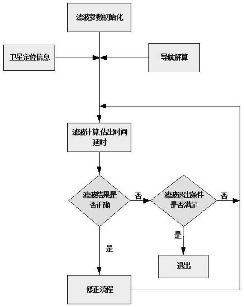
[0040] A time synchronization method for a position measurement integrated navigation system, comprising:

[0041] Increased time delay error in the present invention, formula derivation is as follows:

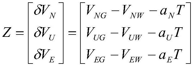
[0042] The first step is to set the speed difference between the satellite positioning device and the inertial navigation system;

[0043] Set the speed difference between the satellite positioning device and the inertial navigation system as:

[0044] δV=V n -V m -a*T Formula(1)

[0045] Where: V n is the speed of the inertial navigation system;

[0046] V m is the speed of the satellite positioning device;

[0047] a is the acceleration of the carrier at this time;

[0048] T is the time difference between the time when the inertial navigation system collects the speed and the time when the satellite positioning device collects the...


PUM


Abstract

The invention belongs to the technical field of integrated navigation, and in particular relates to a time synchronization method of a position measurement integrated navigation system. The method includes four steps. The first step is to set the speed difference between the satellite positioning device and the inertial navigation system; the second step is to update the measurement vector during navigation solution; the third step is to judge the filtering result; the fourth step is to step, correction process. Through the method, the navigation accuracy and reliability of the position measurement integrated navigation system when the synchronous pulse is abnormal can be greatly improved, and the failure of the measurement of the turning moment during the track detection process can be prevented. This method can also be used for navigation calculation when the synchronous pulse of other integrated navigation systems is abnormal, which is practical and innovative.

Description

technical field [0001] The invention belongs to the technical field of integrated navigation, and in particular relates to a time synchronization method of a position measurement integrated navigation system. Background technique [0002] The position measurement device used in track detection has the characteristics of long working time and high measurement accuracy. Therefore, the integrated navigation system can be used to accurately measure the position, attitude, speed and other information of the track detection system. The integrated navigation system is a system based on the inertial navigation system and supplemented by satellite positioning information for integrated navigation calculation. In order to ensure that the integrated navigation algorithm has high reliability and navigation accuracy, the inertial navigation information and satellite positioning information need to be strictly synchronized in time, otherwise the estimated value of the filter will produce ...

Claims


Application Information

Patent Timeline
Patent Type & Authority Patents(China)
IPC IPC(8): G01C21/16G01S19/47
CPCG01C21/165G01S19/47
Inventor 李海强郭玉胜王国锋詹丽娟张吉先艾瀛涛邓继权王海军
Owner BEIJING AUTOMATION CONTROL EQUIP INST
Why Eureka
Try Eureka