Servo motor pressure and gap control device under position mode

A servo motor and control device technology, applied in the direction of mechanical pressure/force control, mechanical device, non-electric variable control, etc., can solve problems such as inapplicability, and achieve the effect of stable gap value and stable pressure value

Active Publication Date: 2020-01-07
BEIHANG UNIV
View PDF9 Cites 1 Cited by
  • Summary
  • Abstract
  • Description
  • Claims
  • Application Information

AI Technical Summary

Problems solved by technology

It is not suitable for occasions that need to control displacement and monitor pressure at the same time

Method used


Image

  • Servo motor pressure and gap control device under position mode
  • Servo motor pressure and gap control device under position mode
  • Servo motor pressure and gap control device under position mode

Examples


Embodiment Construction

[0029] The present invention will be further described below in conjunction with the accompanying drawings and examples. It should be understood that the following examples are intended to facilitate the understanding of the present invention, and have no limiting effect on it.

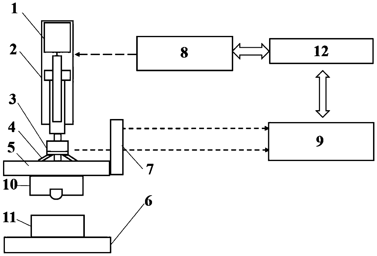
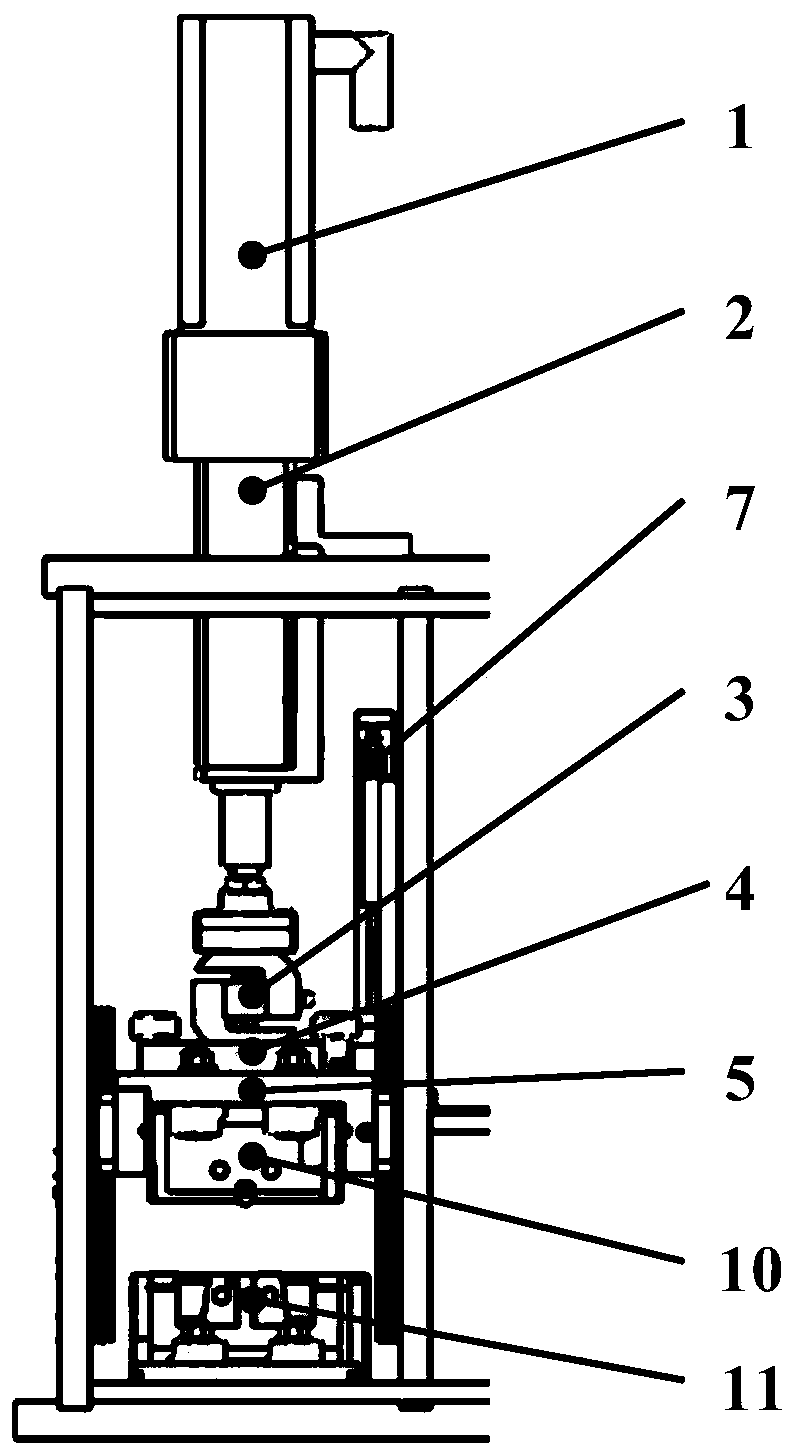
[0030] The servo motor pressure and clearance control device under the position mode provided by the embodiment of the present invention, such as figure 1 and 2 As shown, it includes servo motor 1, servo drive cylinder 2, force sensor 3, disc spring 4, upper mold holder 5, lower mold holder 6, position sensor 7, servo driver 8, I / O system 9, upper mold 10, lower mold holder Die 11 and main controller 12. Among them, the servo motor 1, the servo drive cylinder 2, the disc spring 4, the upper mold base 5, the lower mold base 6, the upper mold 10 and the lower mold 11 form the mechanical part, the force sensor 3 and the position sensor 7 form the sensing part, and the servo drive 8. The I / O system 9 an...


PUM


Abstract

The invention discloses a servo motor pressure and gap control device under a position mode. The servo motor pressure and gap control device is characterized by comprising a servo motor, a servo driving cylinder, a force sensor, an elastic piece, an upper die seat, a lower die seat, a position sensor and a control module, wherein the control module comprises a servo driver, an I / O system and a master controller, the master controller comprises a PLC, a position controller, a speed controller and a current controller, the position sensor is connected with the PLC, a position ring D is built, aposition ring C of an internal encoder of the servo motor and the built position ring D are combined to form a position control dual-closed ring so as to achieve gap control of an upper die and a lower die, the force sensor is connected with the PLC, a pressure ring E is built, and the position ring C of the internal encoder of the servo motor and the built pressure ring E are combined to form a force control dual-closed ring so as to achieve pressure control of the upper die on a test piece.

Description

technical field [0001] The invention belongs to the field of friction testing machines, and in particular relates to a servo motor pressure and gap control device in a position mode, which can provide high-precision and high-stability control for the pressure and mold gap of a low-tonnage plate friction testing machine. Background technique [0002] The study of precise friction conditions such as friction coefficient measurement and friction lubrication analysis in the stamping process is inseparable from accurate pressure and die clearance control devices. Most of the existing friction test control devices at home and abroad use hydraulic control pressure. In the small load range required by aluminum alloy friction test, the control pressure is unstable, and it is impossible to qualitatively and quantitatively evaluate the friction behavior between the aluminum alloy plate and the mold. For aluminum alloy stamping, there is an urgent need for a low-tonnage, high-precision,...

Claims


Application Information

Patent Timeline
Patent Type & Authority Applications(China)
IPC IPC(8): G05D15/01G01N19/02
CPCG01N19/02G05D15/01
Inventor 李小强孟庆阔李东升王烁
Owner BEIHANG UNIV
Why Eureka
Try Eureka