an electric spindle

A technology of electric spindles and mandrels, which is applied to metal processing equipment, maintenance and safety accessories, metal processing machinery parts, etc. It can solve the problems of high working temperature of the back-end bearings, inability to dissipate heat from the back-end bearings, and heating of the bearings to avoid Severe heat generation, ensure the working temperature, and prolong the service life

Active Publication Date: 2020-09-11
永合兴(厦门)精密机械有限公司
View PDF12 Cites 1 Cited by
  • Summary
  • Abstract
  • Description
  • Claims
  • Application Information

AI Technical Summary

Problems solved by technology

[0005] At present, the rear end bearing of the electric spindle usually adopts a double-bearing structure design. When the electric spindle rotates at a speed of up to 100,000 rpm, the bearing heats up seriously. end bearing for heat dissipation
At the same time, there is heat transfer between the electric spindle stator and the back-end bearing, which will cause the working temperature of the back-end bearing to be too high
There are axial runout and radial runout problems at the front end of the electric spindle mandrel

Method used


Image

  • an electric spindle
  • an electric spindle
  • an electric spindle

Examples


Embodiment Construction

[0037] In order to further explain the technical means and effects adopted by the present invention to achieve the intended invention purpose, the specific implementation, structure, features and effects of the present invention will be described in detail below in conjunction with the accompanying drawings and preferred embodiments.

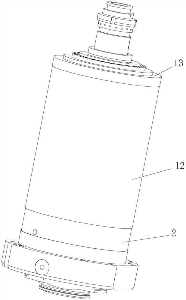
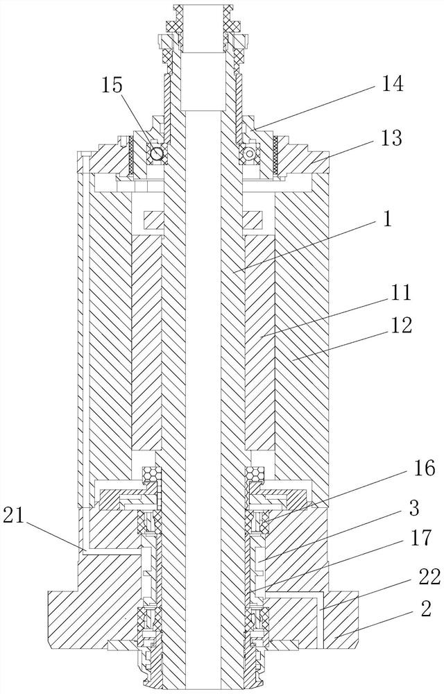
[0038] Such as figure 1 As shown, an electric spindle includes a mandrel 1, a rotor 11 fixed on the mandrel 1, a fixed stator 12, two rear end bearings 16 arranged at the rear of the mandrel 1, sleeved on the rear end The rear end bearing seat 2 on the bearing 16 , the deep groove ball bearing 15 arranged on the front part of the mandrel 1 and the front end bearing seat 14 sleeved on the deep groove ball bearing 15 .

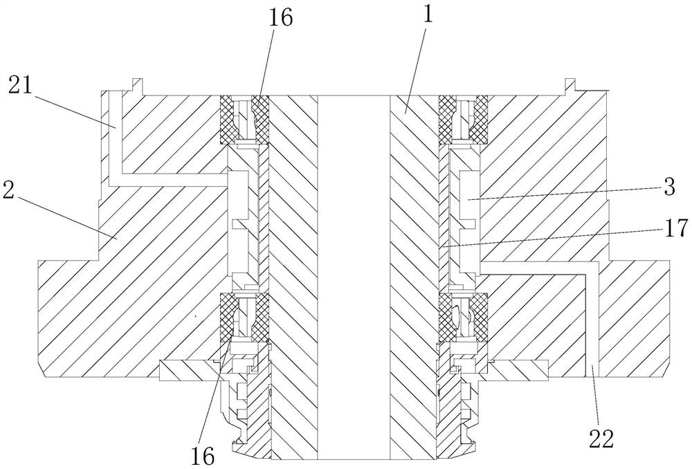
[0039] Such as Figure 2-4 As shown, the first shaft sleeve 17 is sleeved on the mandrel 1 between the two rear end bearings 16, and a cooling chamber 3 is sleeved on the first shaft sleeve 17. The baffles 32 at both ends of the...


PUM


Abstract

The invention discloses a motorized spindle. A core shaft, a rotor fixed to the core shaft, a stator, two rear end bearings arranged at the rear portion of the core shaft, rear end bearing blocks sleeving the rear end bearings, a front end bearing arranged at the front portion of the core shaft and a front end bearing block sleeving the front end bearing are included. The part, between the two rear end bearings, of the core shaft is sleeved with a cooling cavity. The two opposite side walls of the cooling cavity are provided with a first liquid inlet channel and a first liquid discharging channel correspondingly. The parts, between the motorized spindle stator and the rear end bearings, of the core shaft are each sleeved with a heat isolation cavity, and the two opposite side walls of theheat isolation cavity are provided with a second liquid inlet channel and a second liquid discharging channel correspondingly. The front end bearing blocks are sleeved with copper insert bearings, thecopper insert bearings are each sleeved with a front end cover, the bearing blocks and the copper insert bearings are in interference fit, the copper insert bearings and the front end cover are in interference fit, and the front end cover is fastened to the front end face of the stator. The device is simple in structure and good in stability and heat dissipation performance.

Description

technical field [0001] The invention relates to the field of motor equipment, in particular to an electric spindle. Background technique [0002] The electric spindle is a new technology in the field of CNC machine tools that integrates the machine tool spindle and the spindle motor. Together with the linear motor technology and high-speed tool technology, it pushes high-speed machining into a new era. The electric spindle includes the electric spindle itself and its accessories, including the electric spindle, high-frequency frequency conversion device, oil mist lubricator, cooling device, built-in encoder, tool change device, etc. The rotor of the motor is directly used as the main shaft of the machine tool, and the housing of the main shaft unit is the motor base, and cooperates with other parts to realize the integration of the motor and the main shaft of the machine tool. [0003] The electric spindle is composed of a shellless motor, a spindle, a bearing, a spindle un...

Claims


Application Information

Patent Timeline
Patent Type & Authority Patents(China)
IPC IPC(8): B23B19/02B23Q11/12
CPCB23Q1/70B23Q11/127
Inventor 吴学标弓清忠
Owner 永合兴(厦门)精密机械有限公司
Why Eureka
Try Eureka