Transceiving split five-degree-of-freedom measuring device and method with optical path drift compensation

A drift compensation and measurement device technology, applied in measurement/indication equipment, metal processing machinery parts, metal processing equipment, etc., can solve the problems of high cost, large volume, complicated installation and adjustment process, etc., to improve measurement accuracy and compact structure. , the effect of eliminating the influence

Pending Publication Date: 2020-01-10
TIANJIN UNIV
View PDF0 Cites 0 Cited by
  • Summary
  • Abstract
  • Description
  • Claims
  • Application Information

AI Technical Summary

Problems solved by technology

At present, there are some mature static measuring instruments for machine tool errors on the market. For example, laser interferometer is a common instrument for measuring geometric errors of CNC machine tools. It is based on the principle of laser interferometry, but each measurement can only measure one degree of freedom. The cycle is long, and due to factors such as high cost and large volume, it cannot be integrated in the CNC machine tool, and can only be used for offline measurement and calibration of machine tool errors; the XM-60 multi-beam laser interferometer produced by Renishaw in the United Kingdom can Simultaneous measurement of errors in 6 degrees of freedom, but due to the high cost, it is difficult to integrate in CNC machine tools; the laser Doppler displacement measuring instrument of the American Optical Motion Company measures four diagonals through the step-by-step body diagonal measurement method, and identifies The three positioning errors, six straightness errors and three verticality errors of the three axes of the machine tool are also difficult to integrate into the CNC machine tool due to the high cost and the complicated measurement and installation process.

Method used


Image

  • Transceiving split five-degree-of-freedom measuring device and method with optical path drift compensation
  • Transceiving split five-degree-of-freedom measuring device and method with optical path drift compensation
  • Transceiving split five-degree-of-freedom measuring device and method with optical path drift compensation

Examples


Embodiment Construction

[0057] The present invention will be described in further detail below in conjunction with the accompanying drawings and specific embodiments. It should be understood that the specific embodiments described here are only used to explain the present invention, not to limit the present invention.

[0058] The embodiment of the present invention is made up of the following parts:

[0059] The first part, a transceiver split five-degree-of-freedom measuring device with optical path drift compensation;

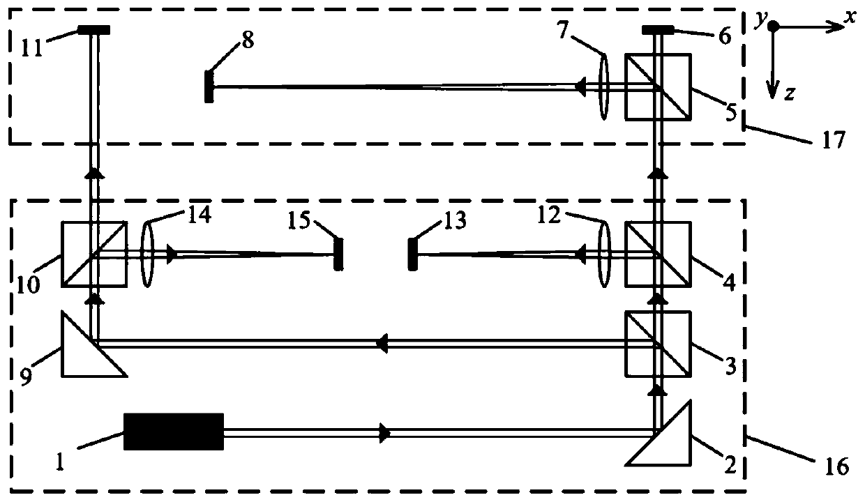
[0060] Such as figure 1 , the transceiver split-type five-degree-of-freedom measuring device with optical path drift compensation consists of a laser 1, a first prism mirror 2, a first beam splitter 3, a second beam splitter 4, a third beam splitter 5, and a first four-quadrant detector 6 , the first convex lens 7, the first two-dimensional position-sensitive detector 8, the second prism mirror 9, the fourth beam splitter 10, the second four-quadrant detector 11, the second conve...


PUM


Abstract

The invention discloses a transceiving split five-degree-of-freedom measuring device and method with optical path drift compensation. The measuring device comprises a laser emitting end and a laser receiving end, wherein the laser emitting end is composed of a laser device, a first prism reflector, a first spectroscope, a second spectroscope, a second prism reflector, a fourth spectroscope, a second convex lens, a second two-dimensional position sensitive detector, a third convex lens and a third two-dimensional position sensitive detector; and the laser receiving end is composed of a third spectroscope, a first four-quadrant detector, a first convex lens, a first two-dimensional position sensitive detector and a second four-quadrant detector. When the measuring device is used, the laser emitting end is installed at a fixed position of a to-be-measured shaft of a numerical control machine tool, and the laser receiving end is installed on a sliding table of the to-be-measured shaft of the numerical control machine tool. The measuring device can realize simultaneous measurement of the pitch angle, the deflection angle, the roll angle, the horizontal straightness and the vertical straightness and realize remote measurement. The influence of laser angle drift on five-degree-of-freedom measurement can be eliminated, and the measurement precision is improved.

Description

technical field [0001] The invention belongs to the technical field of precision measurement and the field of optical engineering, in particular to a transceiver split-type five-degree-of-freedom measuring device and method with optical path drift compensation. Background technique [0002] The machining accuracy of CNC machine tools is one of the main indicators to measure the performance of machine tools, which directly affects the quality of parts. With the continuous improvement of the precision requirements of parts in the machinery manufacturing industry, "how to improve the machining precision of CNC machine tools" has attracted widespread attention from experts and scholars from all over the world. The error measurement compensation method is an economical and effective method to reduce the machine tool error by measuring the original error of the machine tool and calculating the error compensation value by using the spatial error model. A common three-axis CNC mach...

Claims


Application Information

Patent Timeline
Patent Type & Authority Applications(China)
IPC IPC(8): B23Q17/24
CPCB23Q17/24
Inventor 段发阶张聪傅骁刘文正苏宇浩余珍鑫
Owner TIANJIN UNIV
Why Eureka
Try Eureka