
Material lifting device

A material and material trough technology, used in loading/unloading, transportation and packaging, conveyors, etc., to achieve uniform feeding, prevention of overloaded transportation, and simple equipment structure.

Pending Publication Date: 2020-01-10
BEIJING TRT HEALTH PHARMA QINGHAI CO LTD
View PDF0 Cites 5 Cited by
  • Summary
  • Abstract
  • Description
  • Claims
  • Application Information

AI Technical Summary

Problems solved by technology

[0003] In order to solve the problems existing in the prior art, the present invention provides a material lifting device. The equipment arranges the material boxes at a certain interval, and the feeding method adopts the way of actively scooping materials. The feeding is uniform and the structure of the equipment is simple. There is no need to consider whether the material boxes are arranged tightly. The problem of lower blockage caused by unevenness

Method used


Image

  • Material lifting device
  • Material lifting device
  • Material lifting device

Examples


Embodiment Construction

[0021] The technical solutions in the embodiments of the present invention will be clearly and completely described below in conjunction with the accompanying drawings in the embodiments of the present invention;

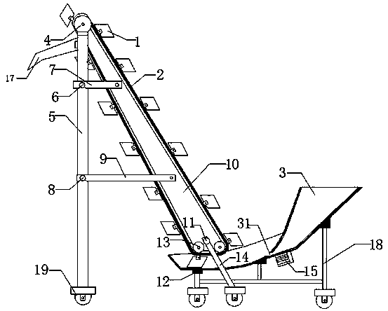
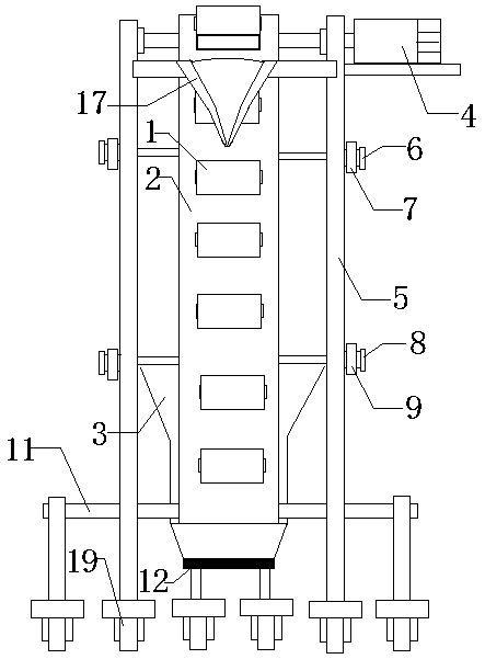
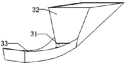
[0022] Such as figure 1 , 2 As shown, a material lifting device includes a material box 1, a chain 2, a material tank 3, a motor 4, a support rod 5, a transverse rib A7, a transverse rib B9, an inner lining frame 10, a transverse bar 11, a sprocket 13, a brace Rod 14; the inner lining frame 10 is arranged obliquely, the two sides of the upper end are connected and supported by two support rods 5, and the two sides of the lower end are supported by two diagonal braces 14 connected by a cross bar 11; the upper end of the inner lining frame 10 is installed There is a sprocket 13, and two sprockets 13 are installed in parallel at the lower end; the chain 2 is arranged on the three sprockets 13; the upper end of the support rod 5 is also equipped with a motor 4 (a reduc...


PUM


Abstract

The invention discloses a material lifting device. The material lifting device comprises a plurality of material boxes, a chain, a material trough, a motor, two supporting rods, cross ribs A, cross ribs B, a lining frame, a cross rod, three chain wheels and two oblique support rods. The lining frame is obliquely arranged. The upper end of the lining frame is supported through the two supporting rods. The lower end of the lining frame is connected with the two oblique support rods to through the cross rod so as to be supported. The three chain wheels are mounted on the lining frame. The chain is arranged on the three chain wheels. The motor is mounted at the upper ends of the supporting rods and is connected with the chain wheel at the upper end of the lining frame through a rotary shaft soas to drive the chain to work. The material boxes are arranged on the chain at equal intervals. The cross ribs A and the cross ribs B are arranged between the supporting rods and the lining frame forreinforcement. The material trough is arranged at the lower end of the lining frame. According to the material lifting device, the material boxes are sequentially arranged at certain intervals, and an active feeding mode is adopted, so that feeding is uniform; and the material lifting device is simple in structure and fast to mount.

Description

technical field [0001] The invention relates to the technical field of material lifting, in particular to a material lifting device. Background technique [0002] Material elevators are often used in food processing production lines. The existing technology mostly uses bucket elevators for powder or granules, such as Z-shaped bucket elevators; when using this type of elevator, the feeding process is controlled by the material itself. The gravity falls into the material box, and then the material box is conveyed to the upper end through the chain, and then the material is unloaded by the gravity of the material itself through the flip of the material box. In order to ensure the improvement of efficiency and not spill when feeding, the material boxes are densely arranged and arranged horizontally. It is necessary to align and move closer to each other in the state. Due to the relative movement between the material boxes, it is difficult to achieve complete seamlessness, which ...

Claims


Application Information

Patent Timeline
Patent Type & Authority Applications(China)
IPC IPC(8): B65G17/12B65G21/10B65G65/06
CPCB65G17/126B65G21/10B65G65/06B65G2201/04
Inventor 陈超宋亚玲汪国泰库进良
Owner BEIJING TRT HEALTH PHARMA QINGHAI CO LTD
Learn More