Perforating gun for horizontal well
A technology for perforating guns and horizontal wells, which is applied in wellbore/well components, production fluids, earthwork drilling and production, etc. It can solve the problems of radial rotation of perforating gun cartridge holders, decreased accuracy of perforating positions, and increased perforating gun Problems such as failure of explosion transmission can achieve the effect of reducing the chance of gun body bursting, reducing frictional resistance, and reducing the loss of jet energy
- Summary
- Abstract
- Description
- Claims
- Application Information
AI Technical Summary
Problems solved by technology
Method used
Image


Examples
Embodiment 1
[0033] see Figure 4-8 As shown, a perforating gun for horizontal wells, including:
[0034] The gun body 42, the gun body 42 is a cylindrical tube, the two ends of the gun body 42 are opened, and the surface is provided with preset holes 421 corresponding to the positions of the perforating charges 20, and the head and tail of the gun body 42 are respectively installed with the gun head and the gun tail.
[0035] The bullet frame 43, the two ends of the bullet frame 43 are fixed in the gun body 42 by the positioning ring 41, and the centerline of the bullet frame 43 coincides with the centerline of the gun body 42, and the perforating charges 20 are discharged on the bullet frame 43,
[0036] The detonating tube is located at the gun head of the gun body 42, and the detonating tube is connected with the detonating cord 50,
[0037] Wherein, the positioning ring 41 includes a ring body 411, a ring hole 412 is opened at the center of the ring body 411, a ring groove is provide...
Embodiment 2
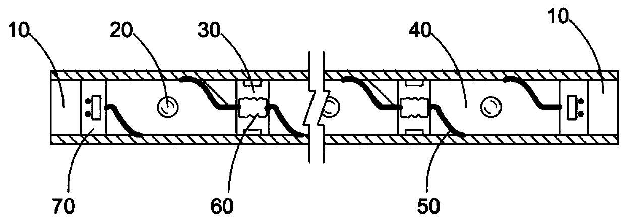
[0043] see Figure 1-4 As shown, the perforating guns 40 are connected by a joint piece 30, and the two ends of the joint piece 30 are respectively connected with the adjacent ends of the two perforating guns 40, and a first sealing sleeve 31 is provided at the joint, through which the joint piece 30 will The two adjacent ends of the perforating gun 40 are connected, and the joint part 30 can be made of flexible material to facilitate the positioning of the perforating gun 40 in the casing under the state of series connection. Improving the connection tightness of the two perforating guns 40 can also prevent debris from entering the perforating guns 40 .
[0044] There is a through hole in the middle of the joint piece 30, and the first detonator tube 32 and the second detonator tube 33 are respectively installed at both ends of the through hole, and the first detonator tube 32 and the second detonator tube 33 are respectively arranged 40, the first detonator 32 and the secon...
Embodiment 3
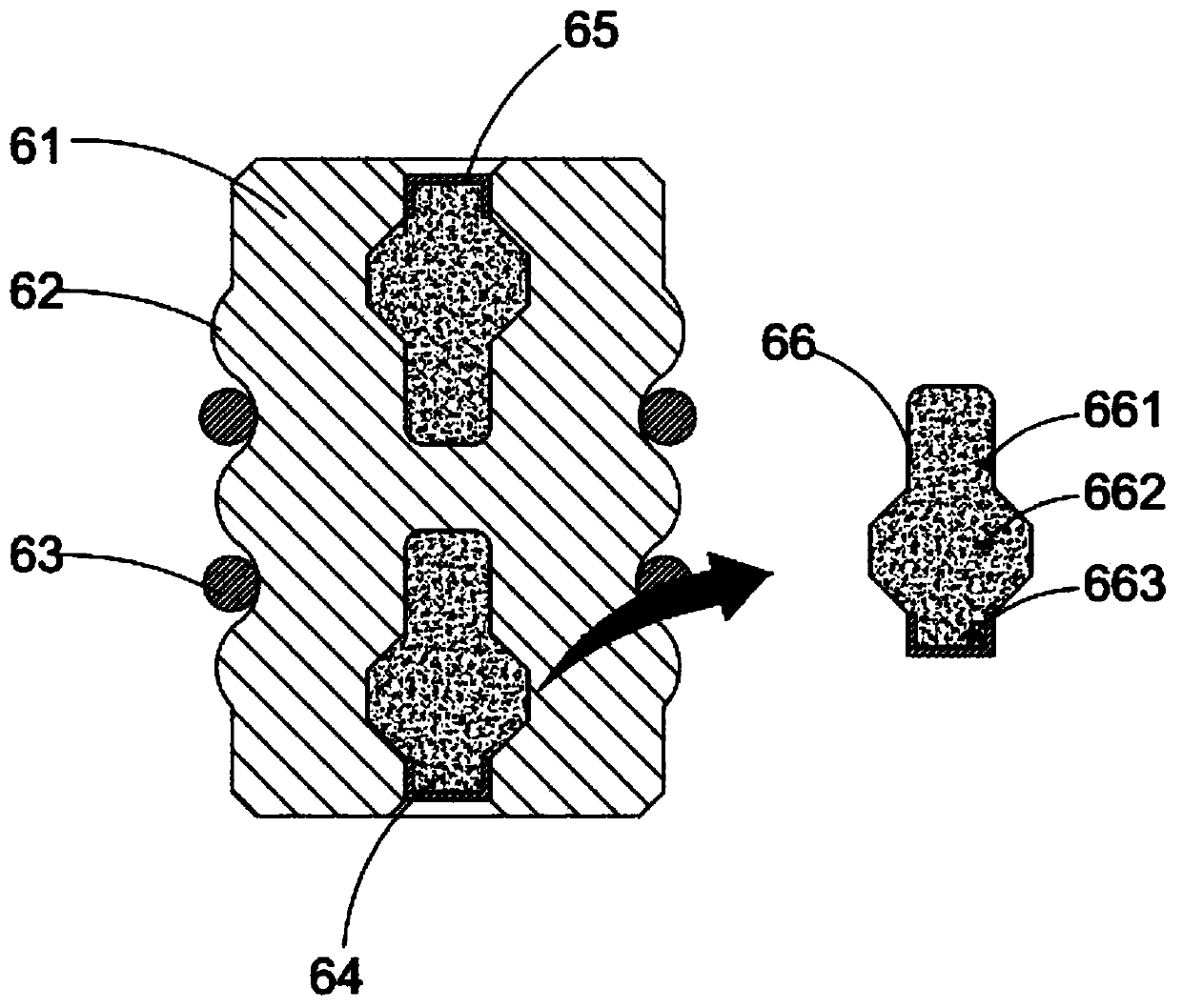
[0050] When the perforating gun for horizontal wells of the present invention is actually used: install the components on the perforating gun 40 in sequence, such as the bullet holder 43, the positioning ring 41, etc., and ensure that the perforating position of the perforating bullet 20 corresponds to the position of the preset hole 421 After completing the installation of a single perforating gun, the perforating guns 40 are sequentially connected in series through the joint piece 30 and the first sealing sleeve 31, and the required perforating guns 40 are connected in series according to the perforating needs. The perforating gun 40 used in the present invention The length of the gun body 42 is 1 meter. During the process of connecting the perforating guns 40 in series, it is ensured that the booster body 61 is arranged in the joint piece 30. At the same time, the two ends of the booster body 61 are connected to the first detonator tube 32 and the second detonator tube at the...
PUM
 Abstract
Description
Claims
Application Information
 - R&D
- Intellectual Property
- Life Sciences
- Materials
- Tech Scout
- Unparalleled Data Quality
- Higher Quality Content
- 60% Fewer Hallucinations
Browse by: Latest US Patents, China's latest patents, Technical Efficacy Thesaurus, Application Domain, Technology Topic, Popular Technical Reports.
© 2025 PatSnap. All rights reserved.Legal|Privacy policy|Modern Slavery Act Transparency Statement|Sitemap|About US| Contact US: help@patsnap.com