Power generation device collecting wind energy through pitching-swinging coupled motion of flapping wings

A technology of coupled motion and power generation devices, which is applied in wind power generation, electromechanical devices, engines, etc., can solve the problems of affecting bird migration, limiting wind energy, and large-diameter fans can only be installed in uninhabited areas, achieving compact structure and low cost. Lightweight, simple structure and effective

CN110671264AActive Publication Date: 2020-01-10WUHAN UNIV
5 Cites 4 Cited by

Patent Information

Authority / Receiving Office
CN · China
Patent Type
Applications(China)
Current Assignee / Owner
Publication Date
2020-01-10

Smart Images

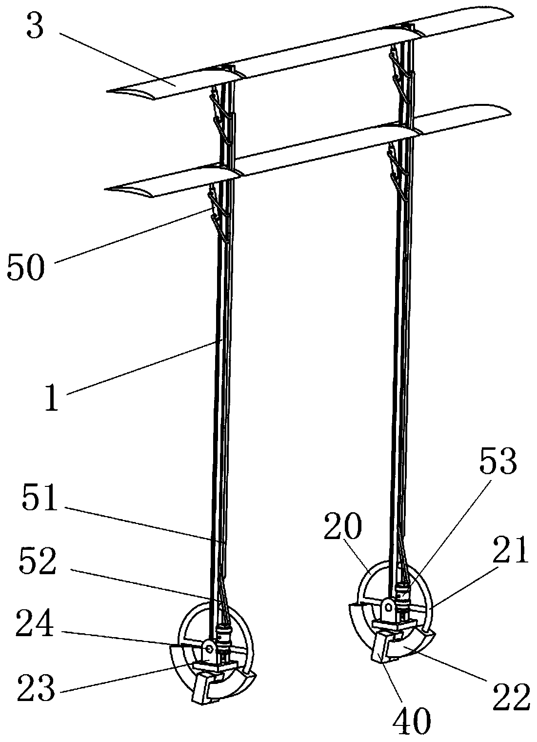
  • Figure 1
    Figure 1
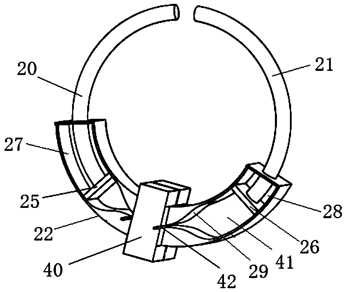
  • Figure 2
    Figure 2
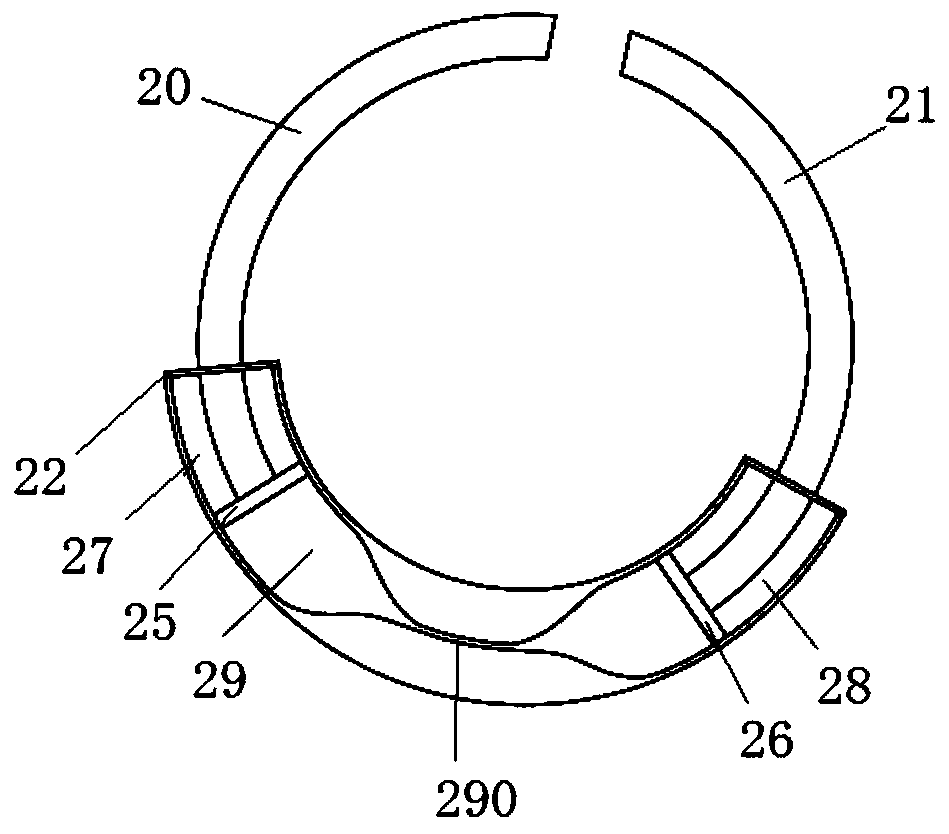
  • Figure 3
    Figure 3
Patent Text Reader

Abstract

The invention relates to a power generation device collecting wind energy through pitching-swinging coupled motion of flapping wings. The power generation device comprises rocking arms, the flapping wings and magnetofluid generators. A telescopic device is hinged to the upper portion of each rocking arm, air cylinder structures rotating back and forth by cooperating with swinging motion of the rocking arms are arranged on the lower portions of the rocking arms, and a sealed chamber is arranged in each air cylinder structure. The flapping wings are movably arranged on the upper portions of therocking arms in a sleeving manner, and the other ends of the telescopic devices are hinged to one sides of the flapping wings. Each magnetofluid generator comprises a C-shaped permanent magnet, magnetofluid which is opposite to the C-shaped permanent magnet and is used for cutting a magnetic field and an electrode connected with the magnetofluid through a circuit. The C-shaped permanent magnets are arranged outside the air cylinder structures in a sleeving manner. The magnetofluid is arranged in the chambers, the magnetic fields generated by the C-shaped permanent magnets are cut in the process that the magnetofluid rotates back and forth along with the air cylinder structures, and therefore voltages and currents are generated and are output through the electrodes. According to the power generation device, the structure is simple and compact, power is generated by providing main power through wind energy, energy is saved, and effective power generation can be carried out.
Need to check novelty before this filing date? Find Prior Art

Description

technical field

[0001] The invention relates to the technical field of power generation devices, in particular to a power generation device that utilizes the pitch-sway coupling motion of a flapping wing to collect wind energy. Background technique

[0002] With population growth, economic development and social progress, people's demand for energy is increasing day by day, but traditional fossil energy is becoming exhausted day by day, and its mining cost and price will gradually increase. Therefore, the development and utilization of renewable energy is the theme of energy development at present and for a long time in the future. Renewable energy includes solar energy, wind energy, water energy (specifically referring to river water energy) and ocean energy, etc. Among them, wind energy is the second largest renewable energy after solar energy, with huge content and potential for large-scale development and utilization. The global wind energy reserves are about 2.84 trill...

Examples

Embodiment Construction

[0024] For a better understanding of the present invention, the following examples are further descriptions of the present invention, but the content of the present invention is not limited to the following examples.

[0025] Such as figure 1 As shown, the present invention provides a power generation device that utilizes the pitch-sway coupling motion of the flapping wing to collect wind energy, including a rocker arm 1, a cylinder structure, a flapping wing 3 and a magnetic fluid power generation device. The upper part of the rocker arm 1 is hinged with a telescopic device. In this embodiment, the telescopic device can be a hydraulic rod 50 with one end hinged to the upper part of the rocker arm 1 and a hydraulic rod 50 connected to the hydraulic rod 50 through an integrated oil circuit 51 and a hose 52. The oil pump 53, here, uses the hose 52 to connect with the hydraulic oil pump 53 because the hose 52 has a certain degree of freedom and expansion and contraction ability, ...