
Anti-blocking structure of flue gas waste heat utilization system for rotary hearth furnace and anti-blocking method thereof

A flue gas waste heat, rotary hearth furnace technology, applied in combustion methods, furnaces, waste heat treatment and other directions, can solve the problems of difficult operation, limited effect, wide range of smoke and dust bonding temperature, etc. The effect of prolonging the blockage period

Inactive Publication Date: 2020-01-10
MAANSHAN IRON & STEEL CO LTD
View PDF8 Cites 1 Cited by
  • Summary
  • Abstract
  • Description
  • Claims
  • Application Information

AI Technical Summary

Problems solved by technology

Due to the complex flue dust of the rotary hearth furnace used to treat solid waste and the wide range of dust bonding temperature, this method is very difficult to operate and the effect is limited. It can only slightly alleviate the problem of heat exchanger blockage
Patent application number 201410467211.6 "Anti-clogging rotary hearth furnace flue gas treatment system and method", invented an anti-clogging rotary hearth furnace flue gas treatment system and method, which is mainly controlled by controlling the temperature to reduce heat exchanger clogging, this method also has the problem of difficulty in actual operation and limited effect, and can only slightly reduce heat exchanger clogging

Method used


Image

  • Anti-blocking structure of flue gas waste heat utilization system for rotary hearth furnace and anti-blocking method thereof

Examples


Embodiment 1

[0035] The anti-blocking structure of the flue gas waste heat utilization system of the rotary hearth furnace according to the present invention, embodiment 1 is:

[0036] The temperature of the flue gas entering the primary heat exchanger of the rotary hearth furnace is 400°C, the emission frequency of the sonic soot blower at the entrance of the primary heat exchanger is 50Hz, and the power of the sonic device is 30,000 acoustic watts; the primary heat exchanger and the secondary heat exchanger The emission frequency of the sonic soot blower installed between the soot blowers is 150Hz, the power of the sonic device is 30,000 sound watts, the maximum sound pressure in the primary heat exchanger is 184dB, the sound pressure around the primary heat exchanger and the secondary heat exchanger Above 150dB, the heat exchanger can be switched in 23 days.

[0037] The anti-blocking structure of the flue gas waste heat utilization system of the rotary hearth furnace according to the p...


PUM


Abstract

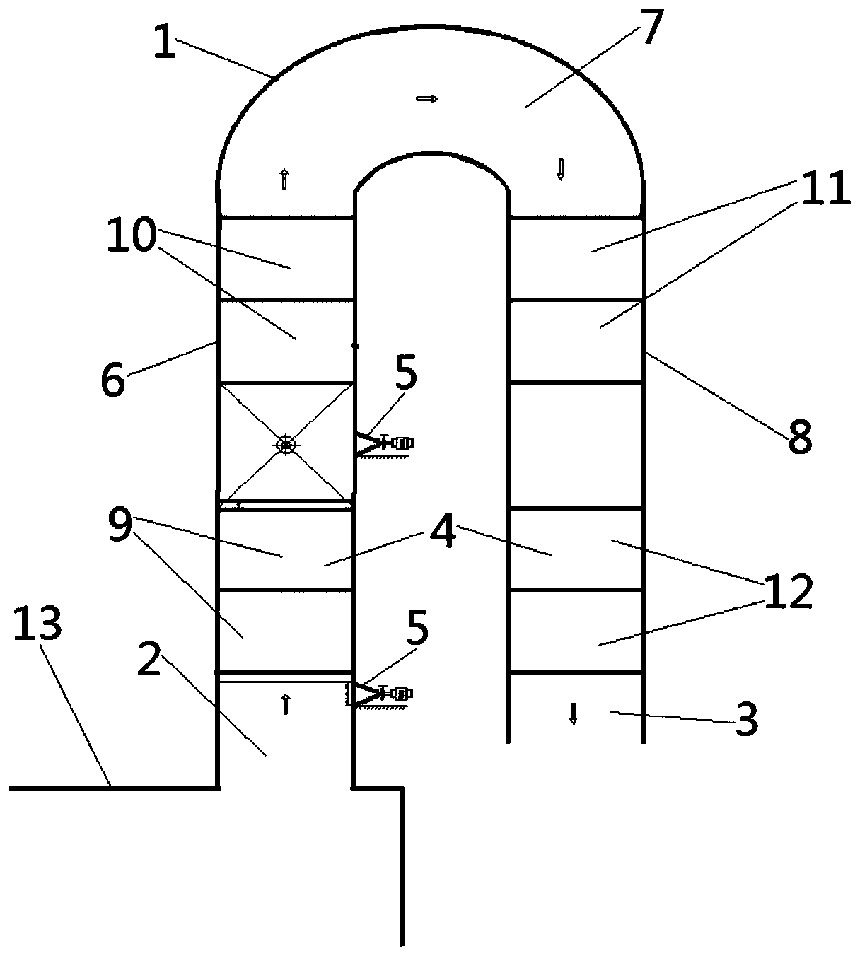
The invention provides an anti-blocking structure of a flue gas waste heat utilization system for a rotary hearth furnace, and further relates to an anti-blocking method of the flue gas waste heat utilization system for the rotary hearth furnace. The anti-blocking structure is applied to the technical field of flue gas waste heat utilization of the rotary hearth furnaces. A flue gas pipeline (1) is arranged on a rotary hearth furnace body of the anti-blocking structure of the flue gas waste heat utilization system for the rotary hearth furnace, a plurality of heat exchangers (4) are arranged between a pipeline inlet end (2) and a pipeline outlet end (3) in the flue gas pipeline (1) at intervals, acoustic soot blowers (5) are arranged at the pipeline inlet end (2) of the flue gas pipeline (1), and the acoustic soot blowers (5) are arranged between every two adjacent heat exchangers (4) in the flue gas pipeline (1). According to the anti-blocking structure of the flue gas waste heat utilization system for the rotary hearth furnace and the anti-blocking method of the flue gas waste heat utilization system for the rotary hearth furnace, a unique sound generator can be arranged at the position to carry out cyclic and reciprocating blowing, so that scaling substances of the heat exchangers are rapidly cleaned, and the blocking period of the heat exchangers of the rotary hearth furnace is greatly prolonged.

Description

technical field [0001] The invention belongs to the technical field of waste heat utilization of flue gas of a rotary hearth furnace, and more specifically relates to an anti-blocking structure of a waste heat utilization system of flue gas of a rotary hearth furnace, and also relates to an anti-blocking structure of a waste heat utilization system of flue gas of a rotary hearth furnace method. Background technique [0002] In recent years, on the basis of digesting and absorbing the development of foreign rotary hearth furnace technology, many companies have successively invested in the construction of rotary hearth furnace devices. At present, the technology of rotary hearth furnaces has gradually become a hot spot in the field of solid waste treatment such as zinc-containing dust and sludge in China. . The inside of the rotary hearth furnace is heat transfer by radiation. The temperature in the furnace is 1200℃~1350℃. The temperature of the flue gas discharged from the r...

Claims


Application Information

Patent Timeline
Patent Type & Authority Applications(China)
IPC IPC(8): F27D17/00F23J3/02
CPCF23J3/02F23J2700/001F27D17/004Y02P10/25
Inventor 李帮平刘自民王宏远徐兆春唐胜卫饶磊桂满城马孟臣张耀辉
Owner MAANSHAN IRON & STEEL CO LTD
Learn More